

Introduction: Palm Arduino Plus


I decided to remove the PCB Eagle files from this project for now, and I will look into it. I will repost it soon.
Sorry for the inconvenience if the problem arise. IF anybody else have the problem with it, please let me know.
Thanks.
Palm Arduino Plus is an extension of Palm Arduino V3, an Arduino compatible board that is compatible with LEGO components.
There are several components added to Palm Arduino Plus such as the motor controller components and some other necessary connectors right on Palm Arduino PCB, so no external motor controller PCB is needed when we want to use Palm Arduino Plus to control motor and servo on the custom built LEGO vehicles such as R/C LEGO® Car (Redux), Wireless LEGO Race Car, R/C LEGO® "The Bull" Buggy, "12 Thumbs" R/C LEGO Dragster, R/C LEGO® Dart Shooter Droid, so no messy jumper wires to be seen.
Palm Arduino Plus can be used as an independent Arduino to develop another type of project that does not use servo or motor. The two 1x14 Arduino out put pins are provided so all digital and analog pins are accessible. To protect the Palm Arduino Plus as we are using it independently, we could built the LEGO case around it as we did with Palm Arduino V3.
Following is the list of the Palm Arduino Plus features:
- Palm Arduino Plus still has the same pin configuration that I designed on Palm Arduino V3, by grouping the communication ports (I2C, Serial Comm. Ports and SPI) on one side of the board, and leave the rest of the pins (Digitals, and Analogs) line up on the other side of the board sequentially.
- Added more standoff holes instead of four corner of the PCB, I used six holes along the width of the PCB, that can accommodate the Lego's stud, so the PCB could more securely sit on to the Lego's bricks or plates than Palm Arduino V3.
- 1x6 pin male header configured for FTDI cable for Arduino Sketch uploading.
- Retain two 1x14 Arduino output pins. So we could use the PCB as an Arduino for another type of project.
- Jumpers for Serial Comm. connectors to use either RX, TX pin on Arduino (D0, D1) or SoftwareSerial RX, TX that assigned to D2, D3 pins on Arduino.
- Added Servo connector (3-pin male header) on to the Palm Arduino Plus.
- Retain the 5V Regulator (that is connected to 6V - 9V Input power supply for motor.) to be used by servo.
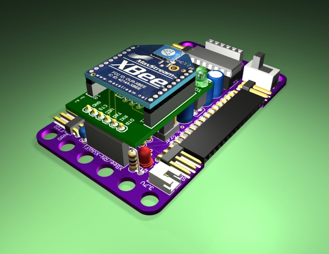
- Eliminated the 3.3V Regulator, and replaced it with 1x2 JST connector to use 3.7V rechargeable LIPO battery as the power supply for Arduino and XBee module (or RX-XV WiFi module or Bluetooth module). See photo 2, 3)
- Added 6-pin female receptacle that is configured for bluetooth (pins compatible for Sparkfun's BlueSMiRF Silver with RN-42 bluetooth module, WRL-10269)
- Added two 2-pin male headers as motor output connectors from L293D/SN754410 motor controller.
- Added 2-pin male header as motor Input power supply (6V-9V battery)
- Replaced the SPST (Single Pole, Single Throw) switch with DPDT (Double Poles, Double Throw) switch to power ON or OFF both 3.7V and 6V-9V power supply at the same time.
Video
- Palm Arduino + Motor Controller (L293D/SN754410) PCB
Note: More videos in Step 4.
Step 1: Kit Components

Kit Components:
IC1 - Atmega328P with bootloader (Adafruit ID# 123)
IC2 - L293D (Jameco# 1341966, Digikey# 497-2936-5-ND) or SN754410 (Jameco# 1054684, Digikey# 296-9911-5-ND)
R1 - 1K Resistor (Radio Shack #271-1321, Jameco# 690865, Digikey# PPC1.0KW-1CT-ND)
R3 - 10K Resistor (Radio Shack #271-1335, Jameco# 691104, Digikey# 10KQBK-ND)
R4, R5 - 1.5K - 2.2K Resistor. I used 2K Resistor (Radio Shack# 271-1325, Jameco# 690937, Digikey# 2.0KQTR-ND)
C1, C3 - 100uF/16V (Jameco# 94289, Digikey# P833-ND)
C2 - 10uF/16V (Jameco# 94221, Digikey# P807-ND)
C4, C5 - 0.1uF/50V (Jameco# 332672, Digikey# BC1160CT-ND)
VR1 – Voltage Regulator 78L05 TO-92 (Jameco# 973831, DigiKey# LM78L05ACZFS-ND)
LED1 3mm LED Green (Jameco# 333201, Digikey# 160-1710-ND)
16MHz Resonator (Digikey# X908-ND)
28-pin IC Socket (Jameco# 112299, Digikey# 3M5480-ND)
16-pin IC Socket (Jameco# 112222, Digikey# A100206-ND)
6-pin Male header, Right angle (Digikey# S1111E-06-ND)
2-pin Male Header, Right angle (Digikey# S1111E-02-ND)
3-pin Male Header, Right angle (Digikey# S1111E-03-ND)
(2) 6-pin Female Receptacle. (Digikey# S7039)
(2) 14-pin Female Receptacle, Right Angle. (Digikey# S5489-ND)
Palm Arduino Plus PCB (I had my Palm Arduino Plus PCB made at third party fabricator, OSH Park, http://oshpark.com, since I can not do it myself in the apartment.)
Note: EagleCAD files for Palm Arduino Plus is provided in Step 2.
Step 2: Design (Schematics and Pin Configurations)


Palm Arduino Plus
I designed the Palm Arduino Plus that similar to an I-shape so it looks different from the Palm Arduino V3. The other reason was that I want to eliminate the unused area underneath the two 1x14 female receptacles of the PCB.
In Palm Arduino Plus, I used the same pin configuration that I designed for Palm Arduino V3 or RevIO, by grouping the communication ports (I2C, Serial Comm. Ports and SPI) on one side of the board, and leave the rest of the pins (Digitals, and Analogs) line up on the other side of the board sequentially (Photo 3 and 4).
I also group the serial comm. pins (TX, RX, VCC, GND) on the rail to to be compatible with the XBee breakout board, such as XB-Buddy Basic Kit, Adafruit's XBee Adapter Board (ID-126), or Sparkfun's Bluetooth Mate Gold (WRL-09358), etc.
In Palm Arduino Plus the 3.3V Regulator was eliminated since I added the 3.7V JST connector for rechargeable LiPo battery to serve that purpose instead.
Instead of using four large stand off holes that can accommodate the Lego's bricks or plates, I made it six stand off holes on each end. So t he PCB could stand on the LEGO bricks more securely.
Design Processes
First, I design (virtual) Palm Arduino Plus PCB in EagleCAD, using exactly the same components as in my Plam Arduino V3. The RevIO PCB is larger than Palm Arduino V3. It is two studs wider and longer on both end.
I planned the layout of Palm Arduino Plus to have the dimension fit with the Lego Modular System, and created the PCB in EagleCAD.
Then send the Gerber files to make the sample PCBs.
After I finished with the PCB layout I created Virtual PCB with CAD program (Autodesk's 3DS Max 8). To make a complete virtual PCB, and rendering out the animation to show the option installation of XBee/RN-XV Wifly module, and bluetooth.
Attached is the zip file contains EagleCad file of Palm Arduino Plus.
Step 3: Assembly


Following are the photos show the assembly sequence that I installed the components on to the Palm Arduino Plus PCB.
Photo 2, 3 Palm Arduino Plus received from fabricator. They are in deep purple color!
Photo 4, 5, 6 I tried the Palm Arduino Plus on the LEGO Bricks to see if there are fit. It needed a little touch up in some holes that only slightly (little tiny off!) off to make it fit to the studs of the LEGO Brick.
The Assembly Sequences:
Photo 7 Shows how I installed the PCB upside down on two 1x8 LEGO Technic Bricks, so I could solder the components on to the PCB. I found it handy using the LEGO bricks as the Palm Arduino Plus PCB holder.
Photo 8, 9 I started with 28-Pin DIP and 16-Pin DIP
Photo 10 The 16 Mhz Resonator and two 0.1uF (or 100nF) Capacitors (C4, C5) installed.
Photo 11, 12 The 10K Resistor (R3) was installed.
Photo 13, 14 The 2K Resistors (R4, R5) installed.
Photo 15 The 1K Resistor (R1) installed.
Photo 16 LED soldering in with the positive (anode) hole is marked with + sign.
Photo 17 The 5V Regulator IC, was inserted into position.
Photo 18 Two 100uF Capacitors (C1, C3) and 10uF Capacitor were installed. These capacitors are polarized so you have to worry about how the leads are oriented.
Photo 19 Installed 1x3 Male Header for Servo.
Photo 20, 21 Installed 1x2 Male Header for motor and another 1x2 Male Header for 6 - 9V power supply for motor.
Photo 22 Installed 2-pin JST header for 3.7V power supply for XBee/Bluetooth and Arduino.
Photo 23 ATmega328 with Arduino Bootloader and L293D/SN754410 IC were inserted into DIP Socket.
There we go! We have completed Palm Arduino Plus!
Step 4: Summary


In the second version I added:
- Double Pole Double Throw switch so we could turn on/off both power supply (3.7V power supply for Arduino and XBee/Bluetooth and 6-9V power supply for motor) at single switch.
- Two 1x3 Jumpers were added so we could used pin D2 and D3 as an option for Software Serial for XBee or Bluetooth, rather than use pin D0 and D1 as the Serial RX/TX for XBee or Bluetooth.
- The Debug LED (pin D13 LED) with resistor were added so we could used it to test the sketch.
Resources
Photo 1 Shows the very first test I did after every components were installed. I removed the L293D/SN754410 motor controller IC before upload the blink LED sketch.
Photo 2, 3, 4, 5 Show the installation option of XBee module and RX-XV WiFly module with the XBee Buddy Breakout board.
Photo 6, 7 Show the installation option of Bluetooth breakout board (Sparkfun's RN-4x Bluetooth Board, I used Bluetooth Mate Silver, WRL-10393 as an example)
Test sketches
Following are the videos of the test of the Palm Arduino Plus of its features.
Note: for the Bluetooth usage, Please look at the Wireless LEGO® Race Car Redux (I'm working on it. Coming Soon!)
Servo
I assigned Digital pin 5 on Palm Arduino Plus to connect to servo output pin.
Following is the Arduino sketch that I used for testing the servo pin connector on Palm Arduino.
Motor
The pins assignment on Palm Arduino Plus for motor output pin from L293D motor controller are digital pin 9, 8, and 7.
Following is the Arduino sketch that I used for testing the motor pin connectors between Palm Arduino and L293D motor controller.
Videos
- Test blink LED
- Test Servo (The Palm Arduino Plus was installed on Wireless LEGO Race Car.)
- Test Motor (The Palm Arduino Plus was installed on Wireless LEGO Race Car.)

Participated in the
Arduino Contest


