

Introduction: Passive Filter Circuits


This instructable is intended to show you how to make several different filter circuits, in particular, low pass and high pass filters, along with a discussion of notch/trap filters and bandpass filters.
What are Filters?
So what is a filter and why would you ever want to build one? Well, you might not end up building any of these circuits by themselves, but you may find yourself integrating them into more complex circuits. You already know what everyday filters do (e.g. air filters, water filters); electronic filters are no different. They take some signal, which in this case is a voltage signal composed of one or many frequencies, and filter out frequencies in a specific range.
High and Low Pass Filters
High pass filters are circuits used to remove low frequency signals and allow high frequency signals. Low pass filters do the opposite and are used to remove high frequency signals and allow through low frequency signals.
Applications
High pass filters are often used in speakers to filter out bass from an audio signal being sent to a tweeter, which could be damaged by the low frequency bass signals. They are also used to remove DC offset or DC bias from a signal, which could otherwise harm amplifiers and other electronic devices. In contrast, low pass filters can be used to filter out high frequency signals in audio being sent to subwoofers that can't efficiently reproduce the high-frequency parts of the audio signal. They are also used in devices such as in the tone knob of an electric guitar (to filter out treble), or in analog synthesizers.
Other Filters
Two other filter circuits that we will briefly discuss are the notch and bandpass filters. Notch filters are used to filter out a very specific range of frequencies, for example to filter out interference of a particular frequency if you happen to live next to a radio station. Bandpass filters do the opposite and will filter out everything but frequencies in a narrow range, and are thus used in radios to tune in to a specific frequency.
Step 1: The High Pass Filter

What You Need
What you put into the circuit:
- One capacitor with capacitance C (in F).
- One resistor with resistance R (in Ω).
- An input signal (ours came from a function generator).
- An oscilloscope (for testing).
What you get out of the circuit:
- A filtered output signal.
How to Build the Circuit
Where do the parts go?
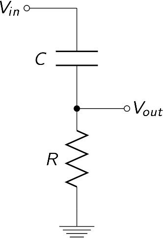
Your input signal is first fed into a capacitor that is connected at its other end to a resistor, which in turn is connected at its other end to ground. Your output signal should be read between the capacitor and resistor.
Test to make sure it works.
If you don't have access to a function generator or oscilloscope, you'll have to trust we tested the circuit for you correctly. We built our circuit as shown:
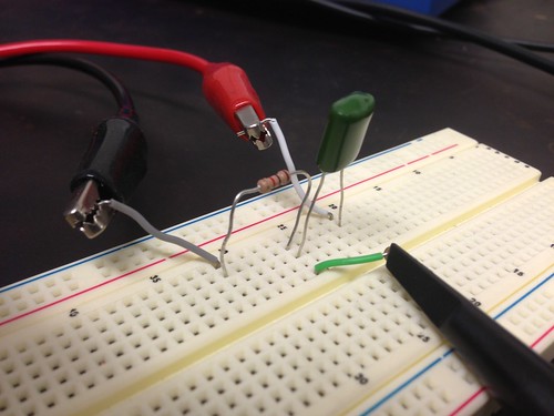
The red alligator clip carries our input signal (from a function generator), the black alligator clip lead to ground, and the green wire carries our output signal, which we sent to an oscilloscope for testing. As we went from low frequency signals to high frequency signals, the result we read on our oscilloscope looked like this:

The yellow curve is our input signal, and the blue curve is our output signal (note that while the yellow curve appears to remain the same, it is because we were changing the frequency scaling on the display of the oscilloscope). At low frequencies, you can see that the entire signal is filtered out and we get almost no output signal. As frequency increases, the output signal becomes larger, until it reaches a point at which it is nearly the same as the input signal. This point is called the cutoff frequency, and we will show you how to find it later. You should also note that the output signal can be phase-shifted from the original input signal, meaning that although the signals have the same frequency, they aren't necessarily "in step", so to speak.
Also, note that while we intentionally inputted signals of a uniform frequency at a time, the circuit will work for compound signals.
The Cutoff Frequency
Calculate the cutoff frequency.
The cutoff frequency is generally considered the frequency at which the signal is attenuated (or filtered). This means that any signal with frequency below the cutoff frequency is considered to be filtered, and any signal with frequency above the cutoff is considered to be "left alone" or unfiltered. So what is the cutoff frequency?

where R is the resistance of your resistor in Ω and C is the capacitance of your capacitor in F.
What does the cutoff frequency mean for the signal?
If you take a look at the ratio of the amplitude of the output signal to the amplitude of the input signal over a wide range of frequencies, you will get something that looks as so

Note that both axes are log-scaled. This means essentially that if you move up from one light gray line to the next, your value is actually increasing by 10 times. This means that if you looked at this plot without log scaled axes, you would essentially see an almost vertical drop off at the cutoff frequency. Any signal or component of a signal that has frequency higher than the cutoff frequency, however, is unfiltered, to a good approximation.
The output signal is phase shifted from the input.
We said earlier that the input and output signals are not "in step" and are actually shifted. This may be fine for some applications, but there are other applications where this may be important. The phase shift changes as the frequency of the input signal changes, just as with the gain, and the plot of this change looks as so

At low frequencies, the output signal is phase shifted by π/2, and at high frequencies the phase shift is almost zero. The cutoff frequency is important to the phase shift because it is the frequency at which the output signal is phase shifted by exactly half of π/2, or π/4.
BUT HOW DID YOU GET THESE RESULTS?!?!
If you really want to know, go check out the Theory section for more information about how the circuit works and how we calculated the gain and phase shift.
TL;DR
- The high pass filter can be made as follows:
- Input - Capacitor - (Output) - Resistor - Ground
- High pass filters filter out signal with frequencies below the cutoff frequency (1/2πRC).
- Since the cutoff is strictly determined by R and C, choose the appropriate resistor and capacitor to cutoff frequencies where you want to
- The output signal is phase shifted from the input.
Step 2: The Low Pass Filter

This section will be similar in content to the section on the high pass filter, so if you've already read that, much of the information found there will apply to low pass filters as well, except with almost everything flipped around.
What You Need
What you put into the circuit:
- One capacitor with capacitance C (in F).
- One resistor with resistance R (in Ω).
- An input signal (ours came from a function generator).
- An oscilloscope (for testing).
What you get out of the circuit:
- A filtered output signal.
How to Build the Circuit
Where do the parts go?
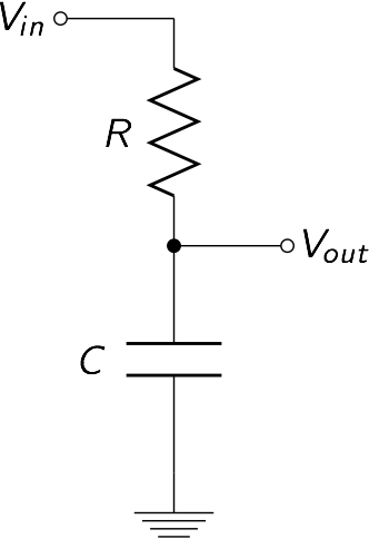
Your input signal is first fed into a resistor that is connected at its other end to a capacitor, which in turn is connected at its other end to ground. Your output signal should be read between the resistor and capacitor.
Test to make sure it works.
If you don't have access to a function generator or oscilloscope, you'll have to trust we tested the circuit for you correctly. We built our circuit as shown:
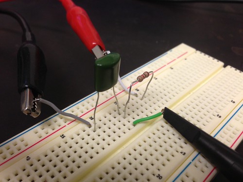
The red alligator clip carries our input signal (from a function generator), the black alligator clip lead to ground, and the green wire carries our output signal, which we sent to an oscilloscope for testing. As we went from low frequency signals to high frequency signals, the result we read on our oscilloscope looked like this:

The yellow curve is our input signal, and the blue curve is our output signal (note that while the yellow curve appears to remain the same, it is because we were changing the frequency scaling on the display of the oscilloscope). At low frequencies, you can see that almost none of the signal is filtered and our output is almost identical to our input. When the frequency reaches the cutoff frequency, the output signal starts getting noticeably smaller than the input signal. From here, as frequency increases, the output signal grows smaller and smaller, until almost no signal is left. You should also note that the output signal can be phase-shifted from the original input signal, meaning that although the signals have the same frequency, they aren't necessarily "in step", so to speak.
Also, note that while we intentionally inputted signals of a uniform frequency at a time, the circuit will work for compound signals.
The Cutoff Frequency
Calculate the cutoff frequency.
The cutoff frequency is generally considered the frequency at which the signal is attenuated (or filtered). This means that any signal with frequency above the cutoff frequency is considered to be filtered, and any signal with frequency below the cutoff is considered to be "left alone" or unfiltered. So what is the cutoff frequency?
where R is the resistance of your resistor in Ω and C is the capacitance of your capacitor in F.
What does the cutoff frequency mean for the signal?
If you take a look at the ratio of the amplitude of the output signal to the amplitude of the input signal over a wide range of frequencies, you will get something that looks as so

Note that both axes are log-scaled. This means essentially that if you move up from one light gray line to the next, your value is actually increasing by 10 times. This means that if you looked at this plot without log scaled axes, you would essentially see an almost vertical drop off at the cutoff frequency. Any signal or component of a signal that has frequency lower than the cutoff frequency, however, is unfiltered, to a good approximation.
The output signal is phase shifted from the input.
We said earlier that the input and output signals are not "in step" and are actually shifted. This may be fine for some applications, but there are other applications where this may be important. The phase shift changes as the frequency of the input signal changes, just as with the gain, and the plot of this change looks as so

At low frequencies, the output signal is phase shifted by zero, and at high frequencies the phase shift is almost π/2. The cutoff frequency is important to the phase shift because it is the frequency at which the output signal is phase shifted by exactly half of π/2, or π/4.
BUT HOW DID YOU GET THESE RESULTS?!?!
If you really want to know, go check out the Theory section for more information about how the circuit works and how we calculated the gain and phase shift.
TL;DR
- The low pass filter can be made as follows:
- Input - Resistor - (Output) - Capacitor - Ground
- Low pass filters filter out signal with frequencies above the cutoff frequency (1/2πRC).
- Since the cutoff is strictly determined by R and C, choose the appropriate resistor and capacitor to cutoff frequencies where you want to
- The output signal is phase shifted from the input.
Step 3: The Bandstop and Bandpass Filters

We will only briefly discuss notch filters and bandpass filters here. These are only the most basic versions of such filters, and thus will only serve the most basic of needs.
Notch/Trap/Bandstop Filter
What is it?
A bandstop filter is a circuit that ideally filters out signals with frequencies in a certain range. This range can be quite large, depending on inherent characteristics of the circuit. The smaller the range of frequencies the circuit filters, the higher the Q factor it is said to have. Bandstop filters with high Q factors are also called notch filters.
Build a simple notch filter.
Using a resistor, a capacitor, and an inductor, you can build a simple notch filter as follows:

What frequencies does it filter?
The center frequency, also called the resonant frequency, around which this circuit will filter can be found as

where L is the inductance of the inductor in H, and C is the capacitance of the capacitor in F.
Bandpass Filter
What is it?
A bandpass filter is a circuit that ideally filters out signals of all frequencies except those in a certain range. This range can be quite large, depending on inherent characteristics of the circuit. The smaller the range of frequencies the circuit allows through, the higher the Q factor it is said to have.
Build a simple bandpass filter.
Using a resistor, a capacitor, and an inductor, you can build a simple bandpass filter as follows:

What frequencies does it allow through?
The center frequency, or resonant frequency, around which the circuit will allow passage can be found similarly as
where L is the inductance of the inductor in H, and C is the capacitance of the capacitor in F.
Step 4: The Theory Behind the Filter Circuits

Image from xkcd.com.
This step is here only to indulge your scientific curiosity and is, by no means, necessary in order to build useful filter circuits.
Voltage Dividers
What is a voltage divider?
A voltage divider, as its name suggests, is a circuit that takes in an input voltage and puts out an output voltage that is equal to some fraction of the input voltage. The circuit itself is simply a voltage source connected to two resistors in series, with the output between the two resistors as shown below.

How does this circuit work?

The key to understanding how the voltage divider works is knowing that the current, I, should be equal across both resistors if there is no current being drawn at the output. Using Ohm’s Law (V=IR, Voltage = Current x Resistance), we see that the voltage drop across each of the two resistors is proportional to its resistance. For example, the input voltage is split evenly across both resistors if the resistors have the same resistances. To put it another way (and actually get a formula for the output voltage) let’s calculate the circuit’s current in terms of the input voltage and total resistance using Ohm's law.

Now calculate the circuit’s current in terms of the output voltage, once again using Ohm's law.

The voltage drop across the second resistor is equal to the output voltage. Note that these two currents are equal, as we said before, so we can set the two equations equal to one another and solve for the output voltage.

This shows that the output voltage is determined by the ratio of the resistance of the second resistor to the total resistance of the two resistors.
A quick example

A Capacitor's Impedance
As you may have noticed, our high pass and low pass filters were just voltage dividers with one of the resistors replaced with a capacitor. Therefore, we can theoretically do the same analysis as above to find out how our filters work, but first we need to understand impedances.
You can think of impedance as a generalized resistance. For example the impedance of a resistor is called resistance, as you know. The impedance of a resistor is just R, the value of the resistance, but what is the impedance of a capacitor? Well capacitors have impedances that are represented by a complex value, 1/(jωC) where C is the Capacitance of the capacitor, ω is frequency of the signal passing through the capacitor in radians (ω=2πf, where f is frequency in Hertz), and j is just the imaginary number i=√-1, (we use j instead of i so we don’t confuse it with current).
Notice that the capacitor’s impedance is frequency dependent. For frequencies close to zero the impedance of a capacitor goes to infinity, however, for very high frequencies the impedance goes to zero. In other words, the impedance of a capacitor looks like a big resistor at low frequencies and like a simple wire with no resistance at high frequencies.
Understanding the High Pass and Low Pass Circuits
You remember the equation that determines a voltage divider’s output,
If we generalized this for impedances we get something like

where Z is just the impedance of our circuit elements, and the tildes or squiggly lines just mean that we are dealing with complex numbers. For a low pass filter we have a resistor at the top and a capacitor at the bottom so

That’s kind of nasty looking but if we simplify we get

Not too bad right?
This last formula is key to understanding why the low pass filter only filters high frequencies. Notice that for low frequencies jωRC is approximately zero and so the output voltage approximately equals the input voltage. Now for high frequencies jωRC is approximately infinite and so we get that the output voltage is almost zero. See how this works? When our complex voltage (made up of various waves with different frequencies) serves as the input voltage for our filter, the high frequency parts of the voltage create an output voltage equal to zero while the low frequency parts create an output voltage equal to the input voltage (i.e. we only get the low frequency part of our signal back).
The same argument we applied to low pass filters can be used on high pass filters, just switch the location of the resistor and the capacitor. We still use the same formula
However, this time

If we simplify we should get

Again, for high frequencies we basically get jωRC ≈ jωRC + 1 so we should get an output voltage equal to our input voltage. For low frequencies we get jωRC ≈ 0 so the output voltage is almost zero. As you can see, as promised we passed over our high frequencies and only filtered out the low frequency.
Cutoff Frequency
As mentioned earlier, the cutoff frequency is a very important value to know for a high pass or low pass filter circuit. How do we actually find it though? The cutoff frequency is defined as the frequency at which the output voltage is exactly 1/√2 of the input voltage. This is the point at which the filter starts the attenuate the input signal. If you solved for this frequency using our equations above, you would find
where ω = 2πf. As you can see, the cutoff frequency is determined strictly by the values we choose for our resistance and capacitance, therefore we can choose exactly where we want our circuit to start filtering signals.


