

Introduction: Pet Deterrent - Keep Them Away From Those Off Limits Areas


The problem: Our cat enjoys trying to "fish" in our aquarium. There are a couple solutions on the market to deter a pet from such things but they are pricey and ugly. I came up with something affordable, unobtrusive, and it fits into our living environment easily. It turns out this is also a perfect solution for teaching the cat that being on top of the kitchen cabinets or in the Christmas tree is also not acceptable.
I used an Arduino Nano with an ultrasonic module to sense when the cat enters the "exclusion" zone. There are actually 3 zones - first an LED blinks, if you get closer the LED blinks faster and beeps, in the final zone there is a steady beep for 2 seconds and then a burst of air. It works like a charm! The first two zones were originally to remind me that I needed to disable the sensor before feeding the fish, but I've found that the beeping is all it takes now to scare the cat off and rarely does it stick around long enough to get the puff of air. I actually built another one of these using just an ultrasonic module and buzzer and it keeps the cat off the top of the cabinets because it thinks the shot of air is coming when it hears the buzzer.
There is a button to turn off the sensor so that it doesn't beep or fire air. When the sensor is off a green LED lights up to remind you. This also keeps track of how many times it "fires" and after a preset number a red LED illuminates to let you know that your air tank needs to be refilled.
If you haven't used an Arduino before, don't be afraid of it! If you are able to backup files to a USB drive, play connect the dots, and at least know what a soldering iron is - there is a good chance you can do an Arduino project. There is a huge community of Arduino fanatics out there that have shared everything they know and it's posted to help you out! My first introduction to the Arduino was just 6 months ago - with all the cool projects and code shared out there it's a fun thing to play with! There are several great instructables that do a great job of explaining how to hook up and program an Arduino for the first time. I need to thank all those that have so willingly shared their knowledge and offered their help as this project is a direct result of what I have learned from you!
Step 1: Parts


I purchase the majority of my electronic parts from eBay and wait the 3-4 weeks to receive them from overseas. Adafruit and Sparkfun are the two places I use when I need things fast.
- Arduino Nano/Micro $3 - Get one that has the USB header on board and the pins already soldered on
- Breadboard or Expansion Shield or Prototype Board $3-$6
- An assortment of different Jumper Wires if using a breadboard or expansion shield
- HC-SR04 Ultrasoninc Module $1.20
- Active Buzzer Module $1.89
- Single Channel Optocoupler Relay 5V-12V depending on solenoid $1.25
- RGB LED 5mm Common Cathode $1.00
- Locking Push Button Switch $0.75
- 1K Ohm Resistors $0.99
- 47uF Radial Electrolytic Capacitor $0.99
- 12V Solenoid Valve for air tank $5
1N4001 Diodes $0.99
The above will cost around $20 if you don't already have some of the stuff laying around as I did. Other miscellaneous supplies I already had laying around and used are:
- PVC pipe / fittings / glue to make an air tank
- Miscellaneous wire for the switch, LED, and ultrasonic module
- Soldering iron and supplies
- Hot glue gun for reinforcing electrical connections
- Air / Schrader valve to put on your air tank to fill it with air
- Miscellaneous fittings to attach air valve and solenoid to air tank
- 12V Power supply with enough amperage to open the solenoid valve under load
- Fish tank air tubing and tubing suction cups
- Terminal Block Connector
- Male Header Pins
- Female Header Pins
- 2 Pin Connector
Step 2: Assembly of Air Tank


I had a bunch of 3/4" PVC pipe and fittings laying around that I used for an air tank. If I pressurize this to 90 PSI there is enough air in it for about 15 "shots" of air. I put a schrader valve on the tank to fill it with air from my compressor. The schrader valves are normally located in with the hot water heating components at your local hardware store.
I bought a cheap 12V solenoid air/water valve off of ebay. Even though the first power supply I used said it was a 2 amp supply it would not operate the solenoid. I'm using a 12V .75 amp power supply that works just fine. Before you attach the solenoid I suggest you verify the in/out ports so you aren't running back to the hardware store for different fittings. Also verify your power supply will open the solenoid when the air tank if fully pressurized.
If you want to avoid air leaks make certain to use plenty of primer and glue when putting the pipe together. Also use pipe dope and/or teflon tape on the threaded fittings.
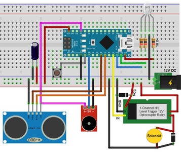
Step 3: Assembly of Electronics


This is where you get to play connect the dots following the wiring diagram I've included. The way I put it together works - but there are several other ways that could also work. I first assembled everything on a breadboard as shown in the schematic and it worked fine. I knew I was going to use this long-term so I then made things more permanent by putting everything on a prototype board. With so few connection on the board I just soldered jumper wires on to make my connections instead of etching a circuit board for just a one time project.
The schematic shows a momentary switch which I originally used and then had a timed delay in the code when pressed. This didn't work well as I found I often needed more time so I changed to a latched push button switch that when pressed lights up an LED to let me know the detector is in "standby".
The 1K Ohm resistors aren't necessary but recommended.
The 47uF capacitor was added after I started testing everything. I was getting random errors now and then and it seemed they happened most often when the air tank was fully pressurized and the air bursts were quick. Thinking it may be the solenoid drawing the voltage down below what the Arduino likes, I threw in a capacitor I had laying around and the problem was solved! I have no idea how to calculate what the "proper" sized capacitor should be, I just threw in what I had and it works. When assembling your board please take note that an electrolytic capacitor needs to be hooked up properly to + and - or it will fry.
UPDATE: I was sent a message encouraging me to add a couple inexpensive diodes to the circuit . Thanks so much for the information! I have updated the schematic including 2 diodes - one on the relay and the other on the solenoid. These are referred to as "Flyback" or "Snubber" diodes. These diodes eliminate flyback, which is a sudden voltage spike across an inductive load when its supply voltage is suddenly removed. These spikes will shorten the life of the relay and solenoid and can cause damage to the Arduino. The line on a diode denotes the cathode or negative side, as you can see in the diagram you are actually putting the diodes in backwards. With the diode in "backwards" it does nothing until there is a voltage spike and then it dissipates it.
The Arduino nano itself runs on 5V and when you program it the USB cable powers it. When using external power like in this project, the Nano has a voltage regulator and the recommended Vin is 7-12V but anything between 6-20V should work alright. These parameters are why I chose a 12V solenoid.
I've read of people having problems with the cheap HC-SR04 ultrasonic modules I used in this project. I ordered 2 of them and both worked just fine. You can Google plenty of simple projects for this module that you can use to test it before you assemble everything. To attach the ultrasoninc module and LED to the board I used an old Cat 5 cable and header pins. As you can see in the pictures I also use hot glue to reinforce the electrical connections.
Step 4: The Code
Programming the Nano is really easy with your Arduino software. There are no additional libraries needed - just make certain you have the right com port and board selected. I have tried to document my code so that it's easier for you to make changes or add additional functionality. I am not a coding expert by any means! I'm certain there are easier and cleaner ways to write this code, this is what I came up with that works for me. If you aren't familiar with the Arduino there are several great instructables that will have you programming it in no time.
Attachments

Step 5: Your're Finished!
I hope I've managed to explain everything enough that you are able to put something similar together. I'm always open to hearing how I could improve this project.

Participated in the
Animals Contest


