

Introduction: Physical Home Automation Interface


The following two videos explain what this project is supposed to do.
An interface conveys information and allows the user to control things. Most home automation platforms rely on a “virtual interface ”. You pull out a smart phone and open the app to see what’s going on with your house and turn lights on and off. That works OK when you’re away. But looking at a virtual representation and parsing the information on the display takes work. It requires focus, and doesn't feel intuitive.
I wanted to make a “physical interface” - a small model house that physically mimics the things I want to know about with my real house. So when the garage door is opened, I want the garage door on the model to also open. This model house could sit on my coffee table, and I can glance at it to see if the garage door has been left opened before going to bed. Or I can have this on my desk at work, connected to my home via VPN. When I’m at work, I can glance at it to see if the front door has been left opened. This physical interface can be as creative or as utilitarian as I make it.
So, in the following steps, I will
- Build a model house to display things like door position, energy usage, and whether a light has been left on.
- Build an energy monitor using the Open Energy Monitor Arduino library, and feed energy use information to the model house and to OpenHAB
- Provide a couple ways of sending door/window position to the model house. Show how the Wink Hub and the Wink "Tripper" contact sensor data can be utilized in a DIY home automation system.
- Use Wink and Arduino to perform outputs, like open/close the actual garage door or turn lights on and off.


The model house has some servos and LED's wired to an Arduino controller. This controller subscribes to MQTT messages that indicate door positions and energy usage, and actuates the servos accordingly. Same idea with the LED that indicates whether a light is on or off. There's a few options for getting this sensor information to the MQTT broker, so I'll detail that in later steps. In the middle of it all is a Raspberry Pi running a MQTT broker (Mosquitto) and OpenHAB. Although OpenHAB is not needed to run the model house, it is needed to provide the interface for the smart phone app, and allow remote monitoring and actuation. Just because I want to have a physical interface doesn't mean I'm ready to throw out the virtual one.
The model house also has two buttons. One of the buttons toggles a zigbee lightbulb on/off. The other button opens and closes the garage door (on the REAL house).
Part 1: House Construction
2) Control options, wiring, & code
Part 2: Inputs (Sensors)
4) Sensor: DIY sensor node option
5) Sensor: Wink Hub & Tripper contact sensor
Part 3: Outputs
6) Lights
Step 1: Model House Construction


I don’t intend this step to be prescriptive. I’m pretty amature when it comes to arts and crafts, so I’ll just show how I built my model house. You’ll want to build it to resemble your own dwelling and reflect the things you care about. Lots of room for creativity here. Some of the components in this picture (like the current transformer) will be used in later steps.
Components:
- (1) Box. It’s up to you how big and what proportions.
- (3) Tower Pro SG90 servo
http://www.dx.com/p/towerpro-sg90-9g-mini-servo-w... - (2) small hinges
http://www.homedepot.com/p/Stanley-National-Hardw... - (some) Adhesive material. I used double stick adhesives from 3M hooks.
- Arduino Yun or Arduino Uno w/ Ethernet shield.
- Buttons
http://www.radioshack.com/mini-spst-1-5-amp-moment... - Stuff laying around the house

Roof
I cut out one of the side flaps of the box and attached it to the other (still attached) side flap to form a roof. I used a small box to provide a structure for the right angle, and later supported it better with a Lego piece. You can probably just use whatever you have around the house to make this right angle.


Doors / Windows
Cut the holes for doors that you want to show. Attach a hinge or two on the door with double stick tape and attach to the house. I know, nothing fancy, so feel free to improvise with what you got around the house. I used 3M double sided foam adhesives, the kind that comes with hooks. I also used these foam adhesive strips to mount the servo motors. For the garage door, the servo motor arm moves the garage door open, and gravity closes the garage door. For the front door, I needed to attach a string on the hinged door so the servo arm can open the door. The yellow Lego piece you see is there to offset the servo from the hinge.

Energy Meter
Nothing fancy. Just cut out an arrow-looking thing and attach it to the servo arm. Cut out a vaguely shrub looking shape and mark it up with a kilowatt scale, and friction fit the servo motor onto the box with the shrub in between.

Above the energy consumption servo, I taped a red LED.
I also have two buttons to control lights and the garage door. These are momentary buttons. The buttons are threaded with a nut on the outside to hold it against the cardboard box wall. On the other side are the metal contacts for wires to be soldered on to.


Step 2: House Construction - Wires & Code


Wiring
Here's the wiring diagram. I made a pretty big mess of the wiring inside the box. If you'd rather just know which wires are on what pins:
- status pin LED: 7
- lighting indicator LED: 4
- Servo 1 (front door): 3
- Servo 2 (garage door): 5
- Servo 3 (shrub of energy use): 6
- Button 1 (Lights on/off): 8
- Button 2 (Garage door open/close): 9
Controller Options
You can use what you're comfortable with and what you have on hand. A less expensive ($20) option is to use an Arduino Uno clone and ethernet shield. I started with that, but that tethered me to the ethernet cable. So I switched it to an Arduino Yun ($65). Much more expensive, but also gave me the freedom to use wifi. The Yun was really easy to use. You basically:
- Connect the Yun to your router via ethernet
- Navigate to the Yun's webpage
- Setup passwords and static IP on your router
- Download the Yun sketch
Attached below are the sketches for both a Arduino Uno and Arduino Yun. They're pretty similar, and except for the ethernet bridge used in the Yun, you can pretty much copy the Yun code over to the Uno. After I made the switch to the Yun, I added the two control buttons. As a result, the Uno sketch doesn't have those buttons.
The video in the first step shows the Arduino Yun. Here's a video using the Uno and ethernet shield. When this video was made, I hadn't installed the two buttons yet, but everything else works the same.

Step 3: Sensor: Energy Monitor


Now that we have a physical interface capable of displaying the energy usage, we need to build a sensor node to read the energy consumption of the house and publish that consumption to the MQTT broker. There's a couple ways to do this. I'm using an Arduino Yun. It's the least complicated method, but not the least expensive. If you want, you can use an Arduino Uno, ethernet shield, and a wireless router to act as a wifi bridge. Or you can use a Pi with the Open Energy Monitor package. I'll just cover the Yun method.

I'm using a $7 current transformer from ebay. You can find the 100A version of the Yhdc SCT-013-000 here . Wire it up according to the wiring diagram above, and upload the Arduino Yun sketch at the bottom of this step. Be sure to modify the code with your MQTT broker IP address. This page for the Open Energy Monitor library is a good reference. Here's the ideal component values.
- Burden Resistor = 33 ohm
- Voltage Divider Resistor = 10k ohm
- Capacitor = 10uF
The picture of my energy monitor doesn't really match the circuit diagram because I didn't have those exact components on hand. I had to use two 68 ohm resistor in parallel because I didn't have the 33 ohm burden resistor. And I didn't have a 10uF capacitor for the rectifier circuit, so I used two 22uF capacitors instead. The series equivalent capacitance is close enough.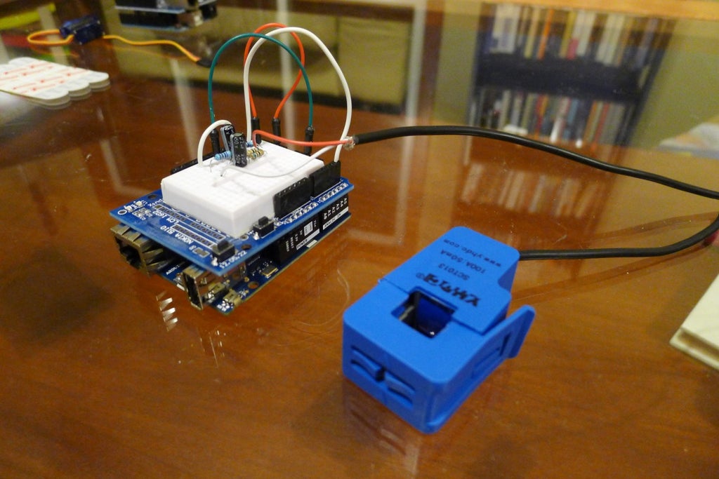

Attach the current transformer on one of the incoming phases of your house. I only had a single 100A transformer, so I'm only monitoring one of the phases. Eventually, I'd like to get more transformers to monitor the other leg of the incoming power and also the branch circuits. Using an actual amp meter, my DIY setup always read 1 amp above the amp meter across different amp readings (see 5th image above). Pretty simple matter to just subtract that extra amp.
OpenHAB
Since we have the data coming in, we might as well also display it on OpenHAB so the data can be graphed. Here's the relevant OpenHAB configuration.

Item Definition
<p>Number itm_smarthome_energy_amps "Energy (amps) [%.1f]" {mqtt="<[mymosquitto:2853:state:default]"}</p><p>Number itm_smarthome_energy_watts "Energy (Watts) [%.1f]" {mqtt="<[mymosquitto:2852:state:default]"}</p>Sitemap
<p>Text label="Energy" icon="firstfloor"<br>{</p><p>	Frame label="Energy Usage"
	{
		Text item=itm_smarthome_energy_amps</p><p>		Text item=itm_smarthome_energy_watts</p><p>		Chart item=itm_smarthome_energy_watts period=h refresh=5000
	} //Frame energy usage</p><p>}//Text label="Energy"</p>
Persistence
Since we're using charts, we need to define some kind of persistence strategy for the energy use. RRD4J is easiest to use, so here's what I have for "/openhab/configurations/persistence/rrd4j.persist".
<p>Strategies {<br>	// for rrd charts, we need a cron strategy
	everyMinute : "0 * * * * ?"
}</p><p>Items {
	DemoSwitch,NoOfLights,Window_GF_Toilet,Heating* : strategy = everyChange, everyMinute, restoreOnStartup

	// let's only store temperature values in rrd
	Temperature*,Weather_Chart* : strategy = everyMinute, restoreOnStartup
	itm_smarthome_energy_watts : strategy = everyUpdate
}</p>
Energy Monitor Screen

Attachments
Step 4: Sensor: DIY Wireless Sensor Nodes

There are a few options for wireless open/close sensors.
In one of my previous projects I used a $5 wireless transceiver to send sensor data over a MQTT gateway. I'm still using this project to get the garage door status to OpenHAB, and in the demo video, that's actually how the model house's garage door reflects my actual garage door status. The detailed code and circuit can be found in this step if you want to use it. It's kind of ugly, but it's in the garage where no one will likely notice.
There is also a light sensor that I'm using to indicate whether a light has been left on. This is also from that previous Instructable detailed in this step. It's part of the Uber sensor that uses a photo resistor to send brightness information wirelessly back to OpenHAB. In this case, I'm simply subscribing to the MQTT topic that indicates light level.
I've also made a battery powered reed switch sensor that uses the same wireless transceiver and gateway in that previous Instructable. However, it's not very good looking. I can't really use it on an interior door or window for aesthetic reasons. So, to over come this problem, I'm using nicer looking consumer-grade reed switch sensors from Wink. Which leads us to the next step.

Step 5: Sensor: Wink Hub


I happened on this blog post from an early Wink Hub user who found a way to root the hub to gain access to a PHP exploit. This exploit allows you to run an "aprontest" utility to control things that have been paired with the Wink Hub. Using this method, I've been able to control lights from the OpenHAB interface.
The most interesting benefit to rooting the Wink Hub is that it gives you local control over lights and sensor status without having to access the Wink server. The Wink Hub and Wink API always needs to go to the internet to contact the Wink server to do lighting control or get sensor status. Now, with this PHP exploit, lighting and sensor operations can be kept to your local LAN. That's great.
I've included a PHP script at the bottom of this step. If you can't open this file, try this link. This script runs on the Raspberry Pi and polls the Wink Hub for the status of two Wink Tripper reed switches. This status is sent to OpenHAB via the REST API. OpenHAB will then publish MQTT topics for these door positions. The controller for the model house then opens or closes the doors by subscribing to these door position topics.
The three OpenHAB configuration files (items, sitemap, and rules) attached in this step are needed to make everything work. They define the contact items that the polling script interacts with via the REST interface. There's also an example script for controlling zigbee light bulb via OpenHAB.
Step 6: Output: Lights


Because of the order that I've covered the configuration files, the previous steps pretty much provided everything needed to control a "connected light bulb" via both the physical interface and the OpenHAB interface. The lights can be any light that the Wink hub supports. Currently, I've tested this with the Cree Connected Bulb and the GE Wink lights. Both work as expected. I'll just throw this video here that better shows how the light sensor and buttons control the smart bulb.
Step 7: Output: Garage Door Opener


The configuration files provided in Step 5 includes most of the necessary OpenHAB items for controlling a garage door. But you still need the something to actually open and close the garage door. For that, I'm modifying parts of a previous Instructable. I made a garage door opener with these components:
- Arduino Clone ($10)
- Ethernet shield ($7)
- Reed Relay ($2)
- Spare garage door remote ($22)
The Arduino controls a reed relay by opening and closing the dry contacts. The button from the spare garage door opener is wired across the dry contact on the reed relay. Connect Pin 5 and GND from the Arduino to the two coil pins (two outer pins) of the reed relay, and the inner relay pins to the button on the garage door remote.
The Arduino subscribes to a MQTT topic and waits for the open/close command. When it sees this topic, it energizes the reed relay momentarily, closing the "button" on the spare garage door remote. The Arduino sketch is attached below. In addition, add the "garage_monitor_rules.txt" to your rules file. This is needed in addition to the rules attached in Step 5. If you don't use the ultrasonic sensor method that I used, this is the part you would need to change to suit your modification.
If your garage door is pretty quite or you want some kind of audio announcement in another part of the house for when the garage door opens, the added rule above can play an audio file. You can hear it in the first video demo about a minute thirty in.
Step 8: Other Thoughts

The decisions made in this project reflect the tools I'm comfortable with, the parts I have on hand, and my priorities for how I want things to work. You probably have a different set of tools, and you have different hardware components readily available. You probably also have different ideas for how home automation should work.
There's lots of flexibility when using MQTT and OpenHAB, and you don't need to do things exactly as I've done it. The controller used to control the model house can be some flavor of Arduino, a Raspberry Pi, or even a Sparkcore. The DIY sensors can be an Arduino or a standalone ESP8266. The only constraint is that the sensor data needs to be published to the MQTT broker somehow. If you have a USB Z-wave stick on the OpenHAB installation, you can use OpenHAB as a Z-wave to MQTT bridge, and utilize Z-wave sensors for door sensing.
Even the Wink open/close sensors could be done differently. If you don't root the Wink Hub, you can use the Wink API to grab the sensor status and post them to OpenHAB, or post them directly via MQTT. This requires using the Wink Server, but it removes the constraint of a rooted hub.
So, lots of ways to do things differently. I tend towards using hardware that is the lowest common denominator, so Arduino and cardboard boxes..

Participated in the
Coded Creations

Participated in the
Move It


