

Introduction: Plug and Play Arduino Temperature Controller


I've seen a few different temperature controller projects here. I wanted to build one, with the following constraints:
- Controlled "dumb" appliance can be plugged directly into the unit. I didn't want to hack into the appliance, but more importantly I wanted to potentially be able to use this with more than one appliance.
- Simple design with simple inputs.
- As modular as possible, so I can pull off components if I ever want to make modifications, or if I want to sacrifice components to be used in other projects (I'm ruthless like that).
I have two specific uses in mind for this project, though hopefully I can come up with more uses somewhere down the line:
- Crockpot Sous Vide!! By controlling a crockpot with a precise temperature controller, I'll be able to do some amazing culinary things.
- Flower-pot hot plate smoker. This design will work perfectly for this type of project as well, though it will probably require a K-type thermocouple (more suited for open air), which I haven't implemented yet. This will be the next phase of the project.
I hope some of the ideas from this instructable will be tweaked and used in different projects.
Let's get cooking!
Disclaimer: This project involves mains voltage, which means you can get fried. Be careful!
Step 1: Materials and Options
Here's what went into my project. I'll link to the specific parts I used, but obviously there are variations
Microcontroller:
- Some flavor of Arduino (mine is a Seeeduino I had leftover from another project, and I did some testing on an Uno)
- Proto shield (any one will do, or go one step further and make your own custom PCB).
Inputs:
- Rotary Encoder with push button, but you could easily use push buttons as user input
- SPST switch (any will do)
- High precision 10k thermistor (and 10k resistor to be used as a reference).
Outputs:
- Solid State Relay (SSR) with a 5V input, at least 10A output that operates at 120VAC.
- 20x4 LCD display for user interface
Other
- Project box (I designed and printed a custom one)
- Power socket
- 3-prong power cord (I took mine from a broken electric kettle). The higher the amperage rating, the better.
- 9V battery connector (optional)
And, of course, whatever appliance you plan to control:
- Crockpot/slow cooker. Having precise temperature control will let you turn your crockpot into a sous vide machine!
- Hot plate. Down the line I plan to modify this and add a K-type thermocouple (better suited for open air), and use it with a hot plate to have a low-cost smoker.
- Room fan or space heater? Get creative!
Step 2: Wiring It Up


I haven't gotten into the habit of making circuit diagrams or schematics before I start prototyping, I just jump right into it. I won't go into soldering technique, but I will mention one thing. Don't forget about insulation, whether it be heat shrink or electrical tape. Don't leave any high voltage connections exposed.
LCD
First I set up the LCD. I did this first, because the LCD is the largest single element and I wanted to be able to choose the way it fit together with the proto shield. I used headers instead of soldering directly to the proto board, so that I could unplug it as needed.
- I soldered male headers (16 pins) to the LCD, then a strip of female headers to the proto shield, positioned so that the LCD will sit mostly on top of the proto shield (or vice versa). I also planned it so that the female header strip on the shield is close to the digital IO side; this will make soldering more convenient.
- I soldered the LCD female headers to their respective pins on the shield, and added the dimmer pot. Adafruit has an excellent tutorial on this. It takes 6 digital pins (mine are on pins 7-12).
Rotary Encoder, Relay Input
Now, real estate on the proto shield will be scarce, since the LCD will be sitting right on top of it. However, I still wanted to use header pins for the rotary encoder and relay, so that I could easily unplug them if I needed to.
- I found some open space where I could put the 5 pins of the encoder. I I wired the encoder pins to Arduino pins 2 and 3 (the Arduino encoder library I used recommended using interrupt pins for best performance), and the ground pin to ground (duh).
- I wired the push button to pin 4 and ground. I was lazy here and used the internal pullup resistors of the Arduino instead of wiring in my own resistor.
- I wired the relay input (also with headers) to Arduino pins 5 and 6. Normally you would hook one of these pins up to ground (or 5V). Since there were two free digital pins next to each other, I used both of them. In the code, I will just set one of the pins to LOW to simulate ground.
Thermistor
The thermistor itself has 2 wires, as it's essentially a resistor with a value that changes with temperature. Much like a potentiometer, which changes resistance with the knob position. Therefore, we need to make a voltage divider circuit and connect it to an analog pin in order to read it. Once again, Adafruit has an excellent tuorial.
- One end of the thermistor will be connected to ground, the other end will be connected to A0 and one end of the 10k reference resistor. The other end of the resistor will be connected to 3.3V (less noisy than 5V), and the 3.3V pin will also be connected to the AREF pin.
- I decided to solder the thermistor and the reference resistor into a JST connector, so that I would be able to unplug the thermistor as a unit. I used a 4 pin JST connector, though I only needed 3 pins.
Relay Output
Now, I didn't solder this up until I was assembling the components into the project box, because I didn't have the proper connectors and soldered it straight up. Either way, I'll talk about it here. And don't forget the heat shrink!
- I stripped the power cord and separated the 3 wires, leaving their individual insulations intact. I used a multimeter to verify which wire connected to which prong.
- The ground prong and the right prong are connected directly to the respective pin on the power socket.
- The left prong (white on my cable) is connected to one of the output pins on the relay (doesn't matter which).
- The other output pin on the relay is connected to the remaining pin on the power socket.
Switch
Finally, I wired up the switch with a 9V battery terminal, and hooked it up to Vin and GND, so that I can use battery power (though I usually prefer USB power when it's available).
Step 3: Put It Together


I'll keep this part short and sweet.
I decide to design my own and 3D print it. I have a printer, and wanted to practice my CAD and design skills, so it was a no-brainer for me.
A couple of things I learned along the way and/or design choices I made:
- I made round posts and holes to mount the LCD. This made the LCD face flush with the front of the box, and the hardware isn't visible from the outside. I ended up making the attachments with small wood screws, and it worked perfectly!
- I did something similar for the relay, since it had similar mounting holes, and the LCD had worked out so well. With this post, the relay is suspended inside the box, instead of attached to one of the walls. This allowed me to design the overall form a bit smaller, since I could have the relay floating on top of the LCD, instead of next to it.
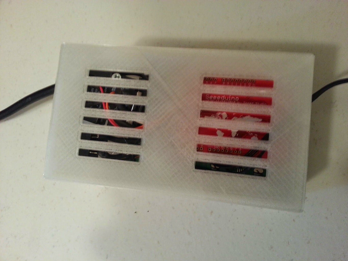
- The holes for the Power cord and the Arduino connector were left open for easy removal.
- The back piece is a very simple interference fit, for easy removal, and some vents were added.
When I examined the lid of my crockpot, I noticed there was a hole in the glass that fits a nub on the handle to keep it from shifting. I drilled through the plastic and fed in my thermistor unit so that it would sit about halfway down into the crockpot when the lid was closed. I hot glued it into place. Done and done!
Step 4: Program
Code is attached, but I wanted to share my approach for temperature control.
I wanted something between:
- "ON if actual temperature is below set temperature", and
- full PID control
PID control is way overkill for this type of application, but the other option is very slow to react, making the actual temperature bounce significantly around the target, taking a long time to settle.
I decided to use the very simple option, but make it just a little smarter. I separated the program into 3 phases:
- Preheat mode: Relay is ON until actual temperature = (set temperature - offset)
- Leveling mode: Simple turns the relay OFF, then finds at what point the temperature peaks
- Maintain mode: This is the very basic "On if Below, OFF if Above" mode
My thinking if that if I used the correct offset, I could be very close to the target at the end of phase 2, and this would minimize the bouncing effect. It seems to work decently well. I did some testing around 134F, which is the recommended sous vide temperature for medium rare for a lot of meats (beef, veal, lamb, pork, poultry) and therefore what I would probably use the most often. I found that for my Crockpot, after heating plain water at full power from ~60F to 130F, the water continued to heat to about 133F after the heat was turned off. Therefore, my magic offset is 3!
Again, my Arduino code is attached. I would be very happy to explain any specifics.


