

Introduction: Portable Pi Video Game Machine


Since discovering the Raspberry Pi and it's tiny size, many projects I previously would've loved to make simply were just not possible. With a little planning, I came up with the Portable Pi machine to play some retro games on. Hopefully this will help some of you who were considering a similar project.
Step 1: Required Items
List of major components used, mostly sourced from eBay:
4.5mm & 3mm clear acrylic perspex (or plexiglass)
Raspberry Pi 3 Model B with heatsinks & 64Gb SD card
7" 1024x600 LCD monitor
12v 8000mAh Rechargeable Li-ion battery
LM2596 buck adjustable voltage regulator
Mini PAM8403 5v amplifer board with volume control & knob
2x 40 x 28mm 3W speakers
360° Swivel Stand
1/4" Tripod mount screw
1/4" Screw adapter for camera flash bracket
12.6V 2A Intelligent Smart Charger
Misc parts:
Power switch
5.5 x 2.1mm DC power jack
3mm Green LED
HDMI connectors
Micro USB connectors
Connecting wire
Spray paint
Old speaker grill
Blackboard vinyl
Double sided tape
Plasti-bond (or Bondo)
Glue (Acrifix 192)
Tools needed:
Jigsaw
Dremel
Drill
Clamps
Router
Sander & sandpaper
Hot glue gun
Soldering iron & solder
Ruler
Permanent marker
Step 2: Starting Out

I started out by collecting the items required bit by bit & testing before deciding on the final design & layout of the case.
The LCD runs off 5V & has HDMI input, perfectly suited to the Raspberry Pi. I decided to run both the LCD & the mini amplifier off the GPIO 5V pins. As I knew space would be rather tight, I picked up some HDMI connectors and made a custom cable, the pins are straight through, 1-1, 2-2, etc so it's easy to make using some light hook-up wire. Audio is supplied by the 3.5mm jack.
I initially ran into a bit of trouble trying to power everything. I picked up a 3.7V Li-ion battery & used a boost regulator to bump it up to 5V. Many other how-to guides I read recommended this, but as this uses the Pi 3 & a bigger LCD screen, I found the unit would draw a little over an amp & the supply just couldn't cope. Only other option was to go the other way and start with 12V & drop it to 5V. This worked much better as the LM2596 is capable of supplying up to 2A reliably. After testing for a couple of weeks, it proved to be a reliable way to power the device.
Step 3: The Power Circuit

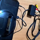
The electrical circuit is rather simple. I chopped the top off the battery as it comes with power connectors & a switch. The switch will be used to power the unit so make sure you don't throw it out. The DC connectors aren't needed and just take up space. Inside are three cells connected in series to give 12V.
I used a green high bright LED as I had a few on hand coupled with a 10K ohm resistor to tone the brightness down. This can be adjusted depending on the LED you want to use.
When the unit is off, the battery's positive terminal is completely isolated from the rest of the components, yet is still able to be charged from the DC jack.
Step 4: Building the Box


Overall dimensions of the enclosure are 230 x 130 x 42mm. The stand is 150 x 110 x 14mm.
I started by cutting out with the front piece & where the LCD would be properly centred. With this known I left the protective plastic over the area on both inside & outside to keep unnecessary scratches to a minimum. Small pieces of 3mm perspex (two glued together) were then glued in place to give the LCD something to mount onto. Spare computer HDD screws will be used.
With the LCD in position, I measured & marked where the Pi would sit. 3mm perspex was cut & four PCB mounting posts (two screwed together to make two longer posts) were used to support the Pi. The side piece was also cut out to give access to the USB & network ports.
Now onto the base, this was constructed of three 4.5mm pieces of perspex, each smaller than the other to create a stepped base. The top two pieces were glued together, then the hole for the 1/4" mount was made 2cm from the back. The bottom was ground out a little using the dremel so the square base of the mount sits flush. The bottom perspex piece was then glued on encasing the mount permanently. It's provides a very neat finish.
Plasti-bond was then applied to the stepped area, allowed to dry & sanded to create a sloped effect.
Step 5: Building the Box Continued


A centre piece for the back was made using two 3mm pieces 5cm wide. The piece behind is slightly wider to provide a bit of a ledge for the back side pieces to rest on. Triangle corner pieces were also made & glued into place.
The following holes were made in this order:
- Volume control
- LED
- Power switch
- DC input
The bottom piece is the 1/4" Screw adapter bracket was glued into place & screwed in from behind before the entire centre piece was glued to the enclosure.
I also masked the screen area slightly overlapping where the protective plastic was to help in case of any paint leakage. This will be covered later on with a vinyl surround.
The edges of the case were rounded off using a router & speaker holes were also cut and edges smoothed off. The whole thing was then sanded using very fine grit sandpaper in readiness for painting.
The two back side pieces were made & adjusted for a neat fit. The protective plastic was left on & masked in some areas to ensure the remain paint free. I wanted to leave these pieces clear so you can see inside the case.
Step 6: Painting


I actually got a little carried away & forgot to take some progress pictures during painting. The case & base had a few light coats of plastic primer applied & then lightly sanded. Several coats of black gloss paint was then applied over the top until an even coverage was achieved.
Step 7: Finishing Up


Once the paint was dry, all the parts were installed & wired up. The speakers were installed first, an old speaker grill was cut up to provide a tiny grills for the tiny speakers which were then glued in with hot glue.
Everything fitted perfectly except for the mini amp, namely getting the volume shaft through the hole from behind. Only way I could get around this was to cut around 3-4mm off the end of the shaft which was just enough to allow it to fit through. Doing this didn't affect anything as the knob covers it up. A little double sided tape was applied to the side & bottom of the battery & then stuck into place.
Using some spare blackboard vinyl, I made a screen surround which covered up the paint edge & makes the front look a little neater.
The swivel mount was then screwed onto the base & the enclosure & tightened with the thumb screw.
All in all, I'm happy with how my little project turned out. Most of the time was spent researching, acquiring & testing the components. Building the enclosure took around a week but could possibly be made quicker if you have more spare time than I do.
Hopefully this helps anyone thinking of doing a similar project. Comments welcome. :-)
Step 8: Cooling Modification

After using the machine for a day or two, I realised things began to get a little warm inside the enclosure, something I didn't consider. So what to do, install a fan of course!
I had a spare 40 x 40mm 12V PC fan which fitted perfectly in the space directly above the Pi. Before installing, I did a little testing: Running on 12V, the fan ran at it's normal fast speed, but was rather noisy, switched to 5V and it was much quieter. Obviously the fan move as much air than if it were connected to 12V, but all we need is to extract the warm air & for this the 5V supply is sufficient.
For a fan guard, I decided to use a little more of the same speaker grill I used for the mini speakers, which I cut to size.
Step 9: Cooling Modification Continued


I removed the left side back cover & marked where the fan will go, roughly 10mm from the bottom. I dremelled out the hole & drilled & recessed the holes for the countersunk screws. Be very careful & take the drilling slowly otherwise you'll crack the perspex. I found out the hard way & ended up having to make a whole new left cover due to an unsightly crack.
I connected the fan by splicing it into the same power cables as the LCD, screwed the fan in & then reattached the back cover - all done!


