

Introduction: Potentiometer-controlled Servo


The coupling application of the potentiometer and servo serves as an important use case in making applications that take advantage of the potentiometer as a rotary measurement of any input. For example, an animatronic helper hand for people with C-6 Quadruplegia or even muscular dystrophy could use the potentiometer as an input for the finger that they can control to aid movement of the other fingers by the use of the servo as a mechanical actuator. This is only one of the many possibilities of the coupling of these two useful electronic components.
Step 1: Tools and Materials

- Arduino 101 or Arduino Uno
- Servo Motor
- Potentiometer
- Breadboard
- Jumper Wires
Step 2: Circuitry
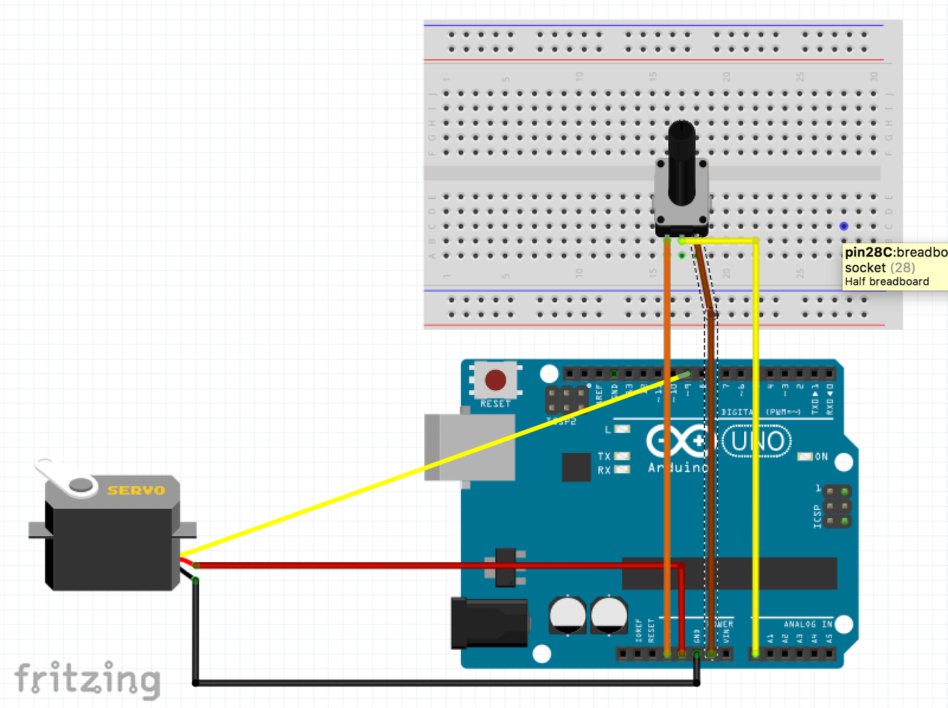

The Arduino will supply two different voltages as mandated by the servo and the potentiometer. That is, 3.3V for the potentiometer and 5V for the servo motor. Since these are the only two electronics that need to be power other is no need to use the power rails of the breadboard.
Wiring the servo to the Arduino
- Connect the red (or sometimes orange) wire of the servo to the 5V pin of the Arduino using red male-to-male jumper wire.
- Connect the black (or sometimes brown) wire of the servo to the GND pin of the Arduino using black male-to-male jumper wire
- Connect the white (sometimes yellow) wire of the servo to pin 9 of the Arduino using a similarly coloured wire.
Wiring the potentiometer to the Arduino
- Connect one of the outer leads of the potentiometer to 3.3V pin of the Arduino with a red jumper wire
- Connect the remaining outer lead of the potentiometer to the other GND pin of the Arduino not already connected to the servo with a black jumper wire
- Connect the middle pin of the potentiometer to the A0 analog pin of the Arduino
Step 3: Code

//include the servo library
#include
//create a servo object called servo1 Servo servo1;
// declare the pins to which the servo and potentiometer is connected. const int servoPin = 9; const int pot = 0;
void setup() { //attach servo1 to pin 9 on the Arduino 101 servo1.attach(9);
}
void loop() { // put your main code here, to run repeatedly: int potValue = analogRead (pot);
// linearly scale the value of the sevo output from the 0 to 1023 range of the potentiometer // to the angle limits by the servo which is 0 to 180 degrees potValue = map(potValue, 0, 1023, 0, 180);
// record the now-adjusted value of the potentiometer to the servo motor servo1.write(potValue);
}
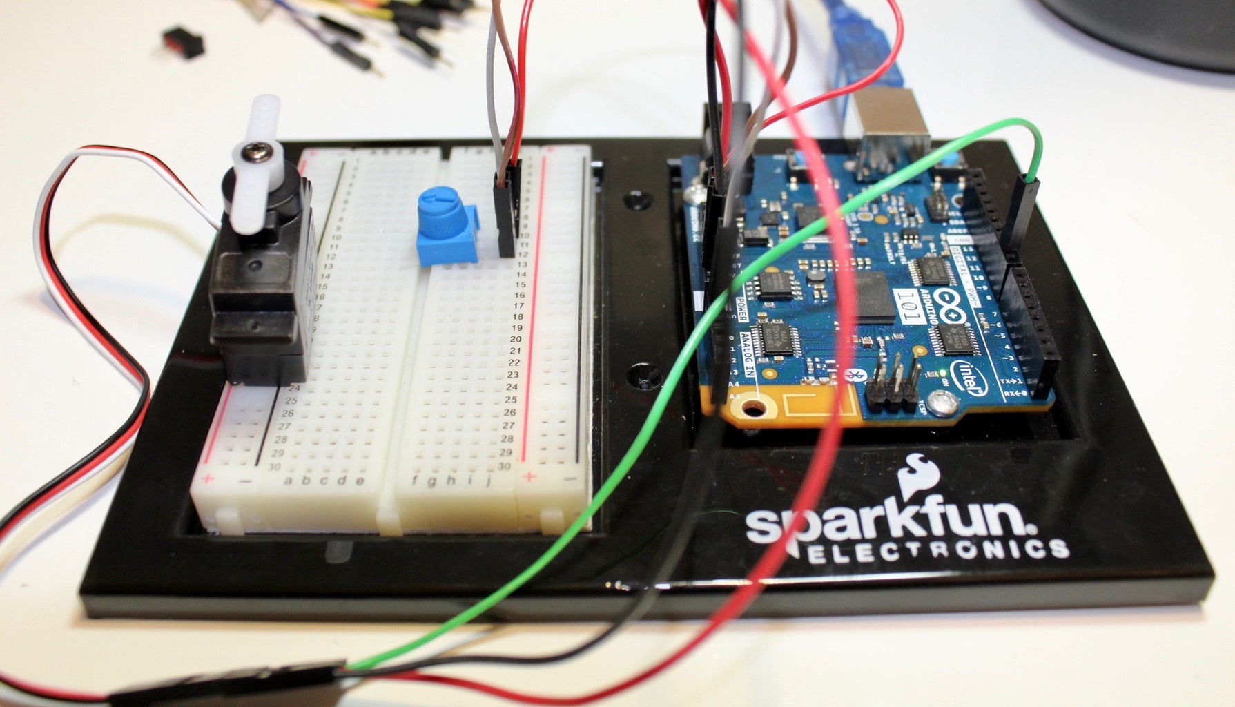
Step 4: Demo
Since the values of the minimum and maximum values of the potentiometer is mapped to the minimum and maximum values of the servo motor, this allows us to control the output of the servo to move linearly with respect the the rotary motion of the potentiometer.
In the demo, you will see that as I turn the knob of the potentiometer it controls the control horn of the servo to move in that specific angle.

Participated in the
Makerspace Contest 2017


