

Introduction: Prosthetic Arm - Marc Vilanova & Marc Mendez

This tutorial shows you how to create a prosthetic arm using Arduino. It will work with a 3D printed arm and a glove to control it with your own arm.
First of all, if the human hand is not moving, the prosthetic one won’t be neither.
On one hand, if the human fingers move, a flex on the human hand will receive it and will send a signal to the prosthetic hand. Then a servomotor will start working so the hand will close. The prosthetic fingers will close depending on the intensity the human hand is being closed.
On the other hand, if the human wrist moves, an accelerometer will receive the signal and send it to the prosthetic wrist, allowing another servo to work.
Moreover, the accelerometer will send a signal to a servo in the prosthetic elbow to move it.
Step 1: Components and Supplies
- 9g micro Servo.
- 2 big Servo.
- 1 Flex.
- 1 9V battery.
- 1 battery compartment.
- 1 Arduino UNO.
- 1 Mini breadboard.
- 1 Switch.
- 1 Arduino cable set.
- 1 Glove.
Step 2: Necessary Tools and Machines
- 3D printer.
- Driller.
- Dremel driller.
- Welder.
- Screwdriver.
Step 3: Apps and Online Services
Arduino 1.8.4
Step 4: Design the Hand and Arm With SolidWorks


First of all, you will have to design the arm you want to control with SolidWorks or any pther 3D model creator app. If you want, you can scale it to do a smaller hand and save 3D material. In our case, we have printed it in 1:1 scale.
To be more useful, you can add platforms on the interior of the arm where all the components will be placed at. We have done two parts of arm, the wrist and the other part of the arm. We also have separated the arm in two halves to be able to put all the components with no difficulties.
To thread the wire that will move the fingers, we created a hole in the fingers and hand.
Step 5: Print the Hand and Arm in 3D


The following step will be to print the 3D model. This can take a long time as in our case, the arm took us about 50 hours to be printed as we wanted. We used a Stratasys Fortus 450 to print everything. For the hand, fingers, and arm, we used ASA. For the phalanges we used ninja flex so de fingers could move properly.
Step 6: Make the Holes for the Wires


Then, you will have to cut holes between the hand and the arm to thread all the wires.
Step 7: Create the Code
Now you will have to create the code that will allow you to move the prosthetic hand. You will need to program a flex and an accelerometer, both connected to two different servomotors. On the bottom of this DIY you have the code we used in order to help you.
Step 8: Check If the Components Work Separately
After creating the code, we will check if the flex and the accelerometer work separately. If they work, we will try to make them work together.
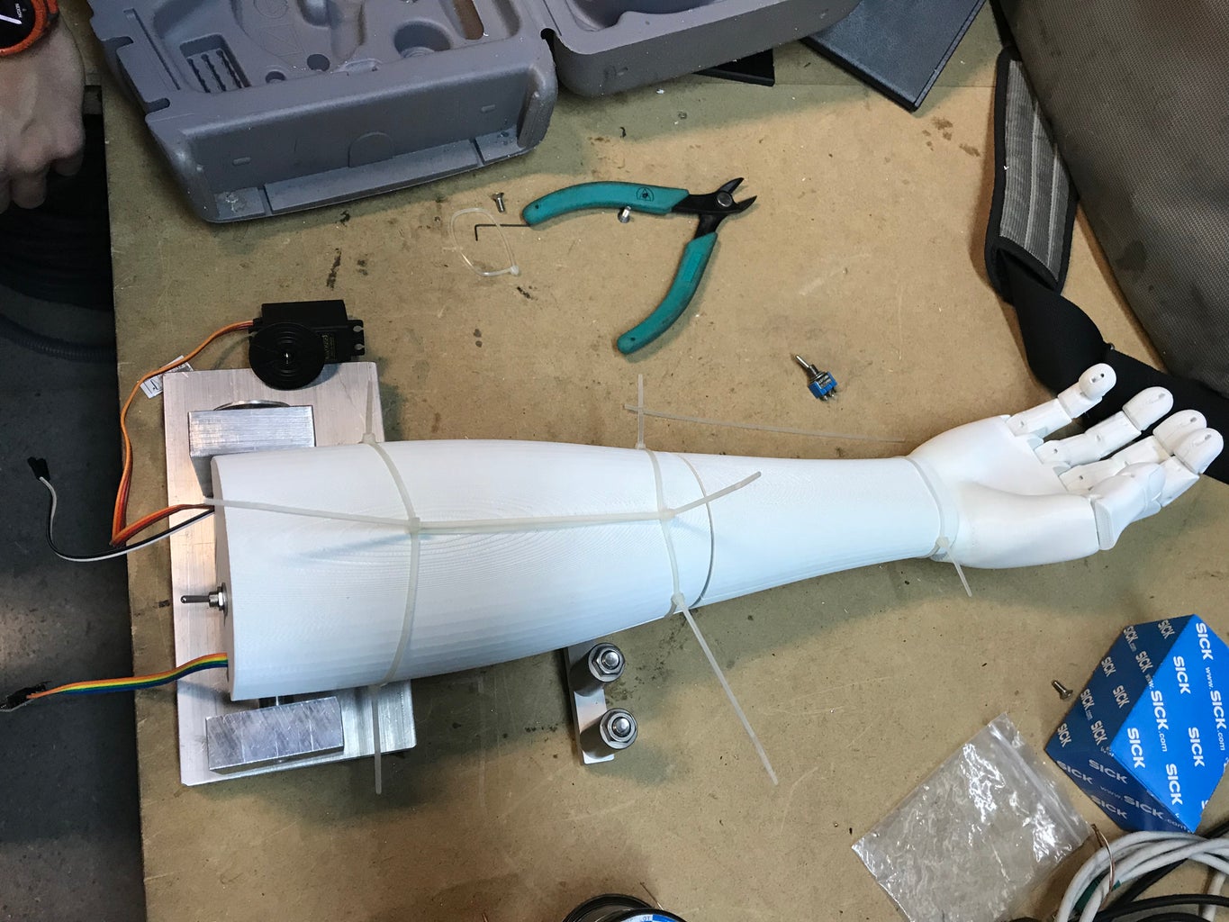
Step 9: Assemble All the Components


Now you will have to assemble all the parts to the 3D printed arm. On the bottom of this DIY you will have the schematics of our wiring. You will have to connect the flex, the accelerometer, the two servos and a 9V battery to the Arduino board. We added a switch to disconnect the battery when the prosthetic hand is not being used.
To move the fingers, we threaded a fishing line in the interior of each finger and hand, directly to the servo. We also added the flex and the accelerometer to a glove connected directly to the 3D printed arm in order to be able to control it.
Then, we made a mount to fix the arm and we used steel. If you do that, you will have to use a lathe and a drill.
Finally, we recommend you to weld the wires, especially the ones that go from the glove to the prosthetic arm.
Step 10: Check If Everything Works
Before closing the two halves of arm you will have to check if all the parts are working correctly, so you won’t have to open it again to redo it.
Step 11: Final Product


We added a counterweight as the elbow servo hadn't enough power to move all the arm.
Step 12: Schematics


Here you can see the wiring diagram we used.
Step 13: Code
For the code we used Arduino 1.8.4. You can use our code to program the prosthetic hand.
// USOS Projecte Hand (part_xyz)
#include  //biblio per controlar perifèrics i microcontroladors
#include  //permet la comunicació amb I2C, per a SLC (clock) i SDA (data)
#include  //llibreria control servo
#define MPU 0x68  //adreca I2C per a la MPU-6050
Servo ServoX, ServoY; //defineix dos imputs del servo
double EixX,EixY,EixZ; //variable de doble presició 4 bytes
int Capcineig, Balanceig; //variable de funcions balanceig i capcineig
// USOS Projecte Hand (part_dit)
#include
const int pinflex = 0;
Servo myServo;
void setup(){// USOS Projecte Hand (part_xyz) Serial.begin(9600); ServoX.attach(8); //output del motor servoX ServoY.attach(9); //output del motor servoY init_MPU(); //inicia el modul MPU 6050
// USOS Projecte Hand (part_dit)
  myServo.attach(10);

}

void loop()
{{
  FunctionsMPU(); // Assignació dels EixX, EixY, EixZ.

  Balanceig = FuncioCapcineigBalanceig(EixX, EixY, EixZ);   //Calcula angle de Balanceig
  Capcineig = FuncioCapcineigBalanceig(EixY, EixX, EixZ);  //Calcula angle de Capcineig
int ServoBalanceig = map(Balanceig, -90, 90, 0, 179); int ServoCapcineig = map(Capcineig, -90, 90, 179, 0);
  ServoX.write(ServoBalanceig);
  ServoY.write(ServoCapcineig);
  Serial.print("Capcineig: "); Serial.print(Capcineig);
  Serial.print("\t");
  Serial.print("Balanceig: "); Serial.print(Balanceig);
  Serial.print("\n"); }
{
int flexpos;
int servopos;flexpos = analogRead(pinflex); servopos = map(flexpos, 600, 900, 0, 180); servopos = constrain(servopos, 0, 180); myServo.write(servopos); delay(25); }
}
void init_MPU(){
  Wire.begin();
  Wire.beginTransmission(MPU);
  Wire.write(0x6B);  // PWR_MGMT_1 registre
  Wire.write(0);     // set a zero, activa el MPU6050
  Wire.endTransmission(true);
  delay(1000);
}
//FUNCIO PER EL CAULCUL DE LANGLE DE BALANCEIG I CAPCINEIG
double FuncioCapcineigBalanceig(double A, double B, double C){
double DatoA, DatoB, Value;
DatoA = A;
DatoB = (B*B) + (C*C);
DatoB = sqrt(DatoB);
Value = atan2(DatoA, DatoB);
Value = Value * 180/3.14;
return (int)Value;
}//FUNCIO PER LA ADQUISICIO X,Y,Z del MPU6050
void FunctionsMPU(){
Wire.beginTransmission(MPU);
Wire.write(0x3B); // inici del registre de 0x3B (ACCEL_XOUT_H)
Wire.endTransmission(false);
Wire.requestFrom(MPU,6,true); // requeriment dun total de 14 registres
EixX=Wire.read()<<8|Wire.read(); // 0x3B (ACCEL_XOUT_H) & 0x3C (ACCEL_XOUT_L)
EixY=Wire.read()<<8|Wire.read(); // 0x3D (ACCEL_YOUT_H) & 0x3E (ACCEL_YOUT_L)
EixZ=Wire.read()<<8|Wire.read(); // 0x3D (ACCEL_YOUT_H) & 0x3E (ACCEL_YOUT_L)
}


