

Introduction: Protect Raspberry Pi Inputs......simple (Part 1)


Can the Raspberry Pi be protected against higher voltages directly connected to its inputs?
The short answer is yes!
If you were to ask me to connect a Raspberry Pi to a 50v / 500mA power supply, I would like to be able to prove it for myself. This is what this instructable will do. It will allow you to prove, to your satisfaction, that it would be safe, BEFORE you connect it to the Raspberry Pi.
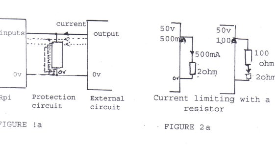
HOW DOES IT DO IT? Connect the protection circuit, one lead to 0v (pin 9) and one lead to the (powered) Raspberry Pi input. (see figure 1a) The external circuit can now be connected to the 0v and the input. (the protection circuit does not need its own power supply.) The external circuit can be up to 50v DC and up to 500mA DC, BUT, It cannot protect against connection directly to a car battery! (>500mA!); It cannot protect against connection to 50v AC (>50v DC), or negative voltages (<0v); It would probably protect against direct connection to a 5v 4amp power supply, (like the one I used in testing the circuit) until the circuit over heated, blew up and then the Raspberry Pi would be blown. It can be connected to logic outputs including 5v to 15v CMOS logic outputs and present safe logic inputs to the Raspberry Pi.(see figure 2b)
If an imaginary 50v / 500mA power supply was connected with a wire to to 0v: result, 500mA current, no volts. Connect it to 2.0 ohm resistor between 0v and the wire,-- 1.0 volt and just under 500mA . A 2.0 ohm resistor will protect, but the Raspberry Pi would receive a logic "O".
Instead, use a USB power supply (5.2v at 500mA ) Now about 1.0v across 2 ohm an still "0".
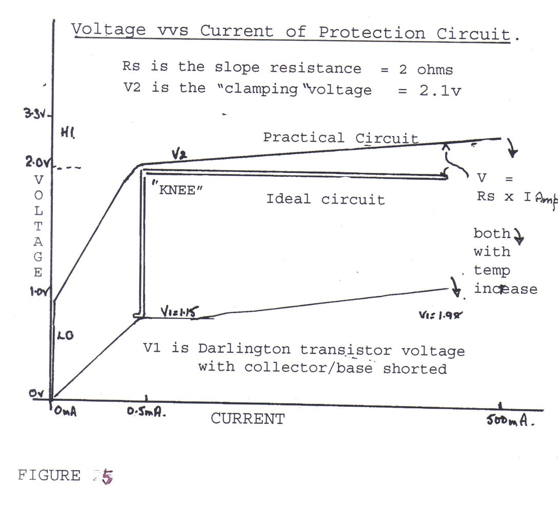
The protection circuit behaves as 2.1v with a 2 ohm resistor (see figure 5). Now about 2.1v +1.0v= 3.1v, logic "1"
(To test the protection circuit using a perfect 50v (100amp) power supply, put a 100ohm resistor in the wire (which would get very hot), or test using a 5v supply and 10ohm resistor (which only gets a bit hot because it is a 5 watt resistor). In each case the current is limited to 500mA (see figure 2a) . With the protection circuit connected the Raspberry Pi is safe, as the voltage is "caught" or "clamped " at below 3v3 ( and the current is less than 500mA so that the protection circuit does not overheat, melt and stop working). With the protection circuit connected, a 5v logic (or 50v logic if it exists) would be read by the Raspberry Pi as "1" or HI. It will also read "0" or LO if the input is less than 1.0v..( See figure 5)).
HOW IS IT DONE? The protection circuit is based on the ULN2803/ULN2003.. In steps 2 and 3, " BUILDING THE CIRCUIT," building and testing two types of protection circuit are described.. For the purpose of testing, resistors are put between the protection circuit and the power supply so that the current can be measured. In practice, if the external circuit is <50v and <500mA, they are not needed. ( NOTE that the total current must less than 500mA from all of the up to 7(or 6) inputs protected. ). In step 4 "A SAFE WAY OF TESTING" with the Raspberry Pi is described (using 3.3v supplies).
Step 1: BUILDING THE CIRCUIT

You will need: --
Something to build the prototype on. Prototype board or Breadboard is OK but at high currents measure the voltage at the ULN pins. If you can-think-upside-down, use "dead bug" and solder wires. Connecting the resistors is a pain.
ULN2803 (or ULN2003 which has 7 buffers, 0v is pin 8, COM is pin 9) Two are needed for type B
Resistors for testing :- 10kohm, 1kohm, 100 ohm (1 watt), 10 ohm (>5watt)
Digital Multimeter
TIP110 or use second ULN
5v (USB?) power supply Preferably an adjustable 12v powersupply.
TYPE A
Connect 0v to pin 9 on the ULN2803. Connect pin 8 to pin 11 , yes input to output of the first buffer. Connect pin 11 to pin 10 (this the COM to the output pin of the first buffer) Check figure 3. That's it.l. One component, no adjustments.
TESTING
Connect a 10kohm resistor from the positive of the power supply to pin 12 (yes, the output of the next buffer). Measure the voltage from pin 11 to 0v ( V1 =1.15v?) and the voltage between pin 12 and 0v (V2 =2.12v?). Work out current ( Power supply volts minus V2 divided by resistor value) Current about 0.3mA.
Change the resistor to 1 k ohm Measure V1 (=1.55v?) and V2 (=2.3v?). Work out current (3mA)
Change the resistor to 100 ohm. Measure V1(=1.64v?) and V2(=2.38v?) Current is about 28mA.
Turn off power supply Change the resistor to 10 ohms. Connect multimeter, then turn on power supply. Measure V2(=2.8v?) and V1 (+1.8v?) Current is about 200mA
Increase the power supply voltage to 7.5v. Measure V2 (=3.09v?) and at current 450mA. ULN will heat up and V2 drop because the base to emitter voltage has dropped and the gain ( hFE) probably increased.
If the measurements are repeated they will be lower (up to -230mV) as the chip (and package) are hot.
When the chip is cool (check using V2 @0.3mA). Overheat the the chip (12v and 16.5 ohm (two 33ohm in parallel,)) V2 is less than 3.3v As the dissipation is 1.65 Watt. V2 will very quickly drop and the ULN temperature rises to 100 degrees C..
Step 2: BUILDING THE CIRCUIT

TYPE B (SEE FIGURE 4)
This type dissipates the heat, about half in one package and half in the other. A second ULN or a TIP110 can be used for the second package. For the TIP110 connect the base to the collector and emitter to 0v (see figure 4). For the second ULN connect pin 9 to 0v, and pin 8 to pin 11 only. On the first ULN disconnect pin 11 to pin 10. The second ULN is connected pin 11 to the first ULN pin 10. The TIP110 is connected emitter to 0v, and collector/base to pin 10 (see figure4).
Test as for the type A. The results will be slightly different; V1 for the TIP110 is 1.47v? at 350mA (the ULN V1 is 200mV more ). The 12v/16.5ohm test results are much better for the TIP110 version as the " clamping" voltage is reduced, thus the total dissipation is reduced, and the heat dissipated in two packages.
Now is the time to connect a 500mA USB directly (No resistor)
It is worth while measuring and plotting the results near the knee. See Note 1. If there are some strange results have a look at the Minor Gotchas and Fixes.
Note 1
Starting from 0v, and the voltage can raised to approx 0.7v and the diodes start to conduct The current increases to 30 or 60 uA (depending on the manufacturer) and then the transistors start to conduct. Note 2 This is the " knee".
Note 2 Just before the knee there is a stage when only one of the transistors turns on This is especially obvious with the TIP110
Step 3: PERFORMANCE

The type A protection circuit has one component and is not adjustable. The component is manufactured by at least 5 manufacturers,( Ti (Texas), Toshiba , Onsemi, Youwang and STM ) and there are minor differences in their data .If the circuit is wired (see figure 3) and connected (see figure 1a) (and the maximum voltages (50v) and current (500mA) adhered to) it will: perform so that: ---
1. the clamping (V2) voltage will always be less than 3.3v
2. the logic level will be "1" (or HI ) for inputs 3.3v to 50v.
3. the logic level less than 1.0v the input will be "0" (or LO)
4. the champing voltage (V2) will not rise as the temperature increases.
5. although the circuit will protect as above up to 500ma, the dissipation should be less than 1.25 Watt continuous
6. Up to 7 inputs can be protected but the total current must be less than 500mA and dissipation less than 1.25watt.
MINOR GOTCHAS AND FIXES
1 Multimeters. Most have 300mA fuses in the current ranges Over ranging at 500mA can be too much.
2 Your multimeter may read low by 1% (?battery?) so don't used two multimeters without calibrating one against the other.
3. The tips of multimeter probes get coated with oxides, grease, solder flux etc.
4 I found that the resistance between 0v (pin 9) and the power supply 0v was 0.35 ohms.........that is 174mV at 500mA. (This was on a breadboard)
5. Work out the currents by measuring the resistor, (it may not be what you thought it was) Use that to divide into the voltage drop across the resistor to get the current.
6. When measuring at higher currents check that the power supply voltage hasn't dropped.
7. The outside of the ULN package gets hot (and cools) slowly. The micro-chip heats very quickly and this affects the readings quickly. Unfortunately, the package heats the micro-chip whilst it cools down
8. As the clamping voltage drops as the temperature rises, so the result will look better as the ULN gets hot. At 500mA the temperature rise will cause the clamping voltage to drop by 350mV maximum.
9. The circuit does not work with the TIP110 below 5mA as the 300ohm resistor (see figure 4) makes it non-linear. This can be fixed by a 3.9 k ohm resistor from the 3.3v supply to the collector/base of the TIP110 (Alternatively a LED and resistor as an indicator)
10. Plot the results using a logarithmic scale for the current i.e. scale 1,10,100,1000mA not 10,20,30,etc..
Step 4: TESTING SAFELY

To test safely use a 3.3v power supply with a 10 ohm resistor (a 4 amp 3.3v power supply can overheat the protection circuit (current 500mA) but the Raspberry pi will not be damaged. Don't use the Raspberry Pi's 3.3v as is only good for 50mA.
For 3.3v the Raspberry pi should read "1". Write a program for the Raspberry Pi , which reads the tested input and lights a (red) LED on an output pin if it is "1" and another (green?) LED if it is "0". Lower the power supply voltage (or use a potentiometer, with wiper to Pi/ protection circuit) and whilst watching the red LED measure the voltage (V2) The voltage should drop to less than 2v and the red Led go out.
The logic test circuits in figure 2b can be used with 3.3v supply
All the buffers on the ULN can be used as protection circuits ( except pin11 on TYPE A) .
If a different package of ULN 2803/2003 buffers is used the result should be similar (except if they are thermally torture like mine!).
If a package is used as a protection circuit the other buffers cannot be used as normal inverters (logic input at input and output taken from the output.); the output LO is 0.7v (ok) but HI will be the clamping voltage. Very odd!. (Note see " part 2" THERE ARE OTHER WAYS") In the TYPE B the other buffers are not affected in the second ULN.!
Yes there are other ways of protecting the 3.3v logic inputs with better performance. They allow the other buffers to be used. They can be used bidirectionally, that is they protect the input and allow the same Raspberry Pi pin to be used as an output. The clamping voltage (V2), the resistance (Rs) can both be altered, simply. Still based on ULN buffers.
PART 2 THERE ARE OTHERS WAYS............


