

Introduction: Prototype Arduino-Raspberry Pi Soundboard
The prototype soundboard created with an Arduino and Raspberry Pi is meant to be a simple way of playing 4 different sounds or noises while having the option to switch sound sets with a knob and display the current sound set with an LCD screen.
*Please note: The code for the project is 99% complete, but is not functional.
The Raspberry Pi controls the 16x2 LCD screen and the rotary encoder while the Arduino reads the analog inputs from force sensitive resistors (FSRs) and sends a signal to the Arduino to play a sound. We both had never used an Arduino or Pi previous to this class, but our professor gave us all of the necessary tools and guidance to easily code and build this project. TinkerCad, a free online 3D modelling tool by AutoDesk, was used to model our project.
The most difficult part of the project was finding a way to get the Arduino and Raspberry Pi to communicate with serial communication. We originally only wanted to use the Pi for the entirety of the project, but we needed the Arduino in order to read the analog signal from the FSRs. We were easily able to send lines of words or numbers from the Arduino and display it on the Pi, but where the issue came was when we tried to read those values into Python and implement them into condition statements to process them.
Skills Required
- Simple understanding of C/C++ for Arduino coding
- Simple understanding of Python for Raspberry Pi coding
- Knowledge on how a breadboard is wired
- Basic 3D modelling skills
- A desire to learn and expand programming, wiring, and building something kinda neat
Part List
1 x Raspberry Pi 3
1 x Elegoo Uno OR Arduino Uno
1 x 830 Tie Breadboard
1 x GPIO Breakout Board (RSP-GPIO)
1 x Ribbon Cable for Breakout Board
4 x Small Force Sensitive Resistors
1 x Basic 16x2 Character LCD Screen
1 x Rotary Encoder Module
24 x Male to female wires
10 x Male to male wires
4 x 10k resistors
1 x 10k potentiometer
1 x Garden foam knee pad (dollar store)
Step 1: Test the FSR With the Arduino

We first decided to try out the FSR with the Arduino. The FSRs send an analog signal and therefore we had to use an Arduino as the Pi doesn't receive analog without other circuits. We wanted to test thresholds to make sure that the presses were at a good pressure. We found it to be around 150 out of a total 1000. The serial plotter on the Arduino IDE was very helpful for this step.
Step 2: Draw Out the Plans for the Board


We then drew up and measured the plans for the board. We wanted to have 4 pads to play sounds with, a spot for an LCD screen to display the current sound group, and a rotary encoder to change the sound group.
Step 3: Model the Board in TinkerCad


After the plans were drawn up, we modeled the board on an online, free, 3D modelling website called TinkerCad by Autodesk. We highly recommend it for those of you who don't want to spend tons of money on big 3D modelling software as it is easy to use, cloud based, and has full support for 3D printing.
After it was modeled, we had to split it into 2 pieces in order to fit it on the printer. It printed off really well, but my mistake was not sizing the LCD screen slot very well (don't make that mistake!) We've uploaded the left and right side .STL files if you wish to check them out.


Step 4: Test the LCD Screen

We had already used the screen on the Arduino and it was very easy to setup. However, it was more difficult to run it with the Pi. With several troubleshooting hours on Google and fidgeting with wires, we finally got it to work. Please see the final Python code at the end to see how it worked. We used a couple websites to help us wire it and write the code.Check them out:
Step 5: Test the Rotary Encoder With the LCD Screen

We then wanted to see if we could make the LCD screen change it's text when the encoder was rotated. The encoder doesn't have a set amount of angles or rotations, so in the code we counted how many times it was rotated clockwise or counter clockwise and made it count to 3. If it went over, it would go back to 0, and if it went under 0, it would go back up to 3. Those numbers can be set for however many sound sets you like, but we only ever ended up testing one sound set. Make sure your sounds are in the same folder/location as where the main Python code is being executed.
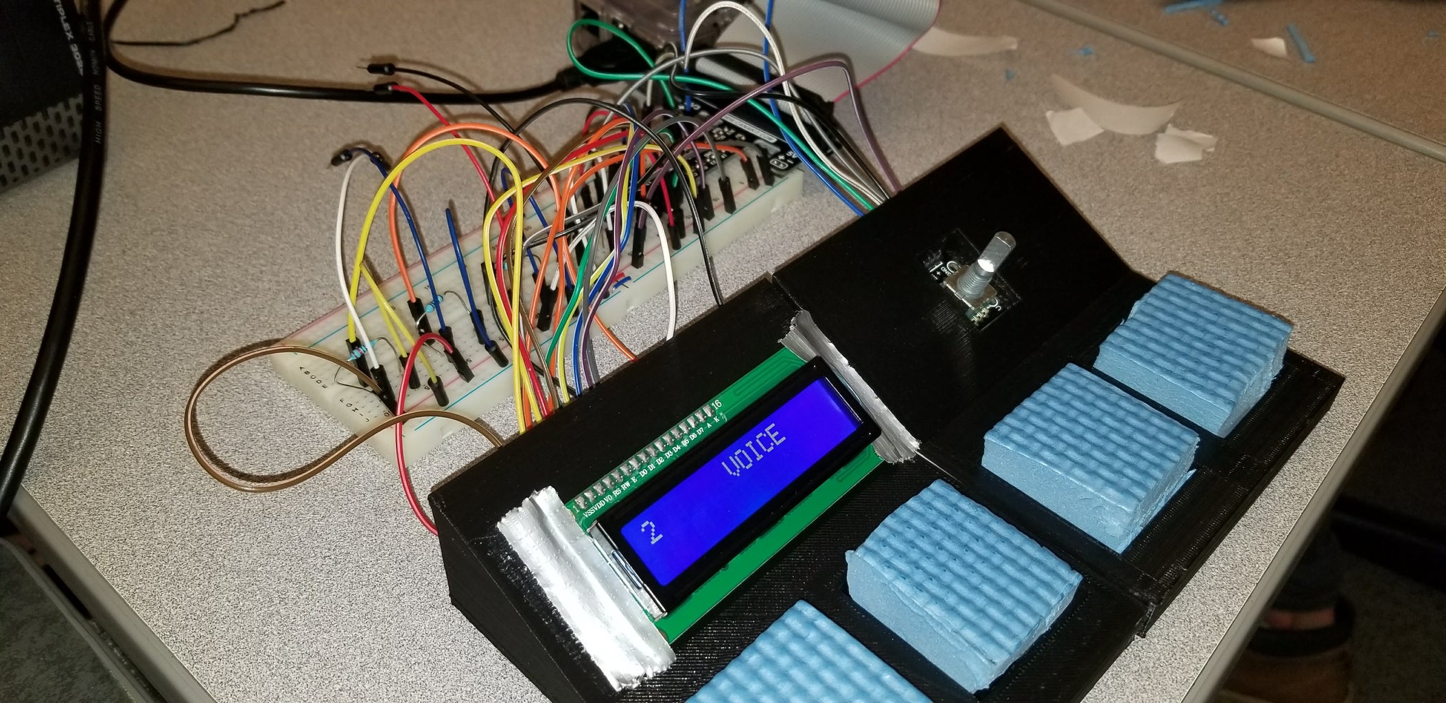
Step 6: Assemble the Board


The FSRs slide under the four different slots. We centered them and taped them down. We recommend duct tape or maybe even gluing because simple scotch tape was terrible at sticking to the 3D printed material. After a quick trip to the dollar store, we found a soft yet squishy garden knee pad that we could cut into four pieces to use as the buttons for the board. We cut them so that they were able to fit snuggly in their spots so that they could stay in place, but also be easily removed if need be.
Step 7: Wire It All Up

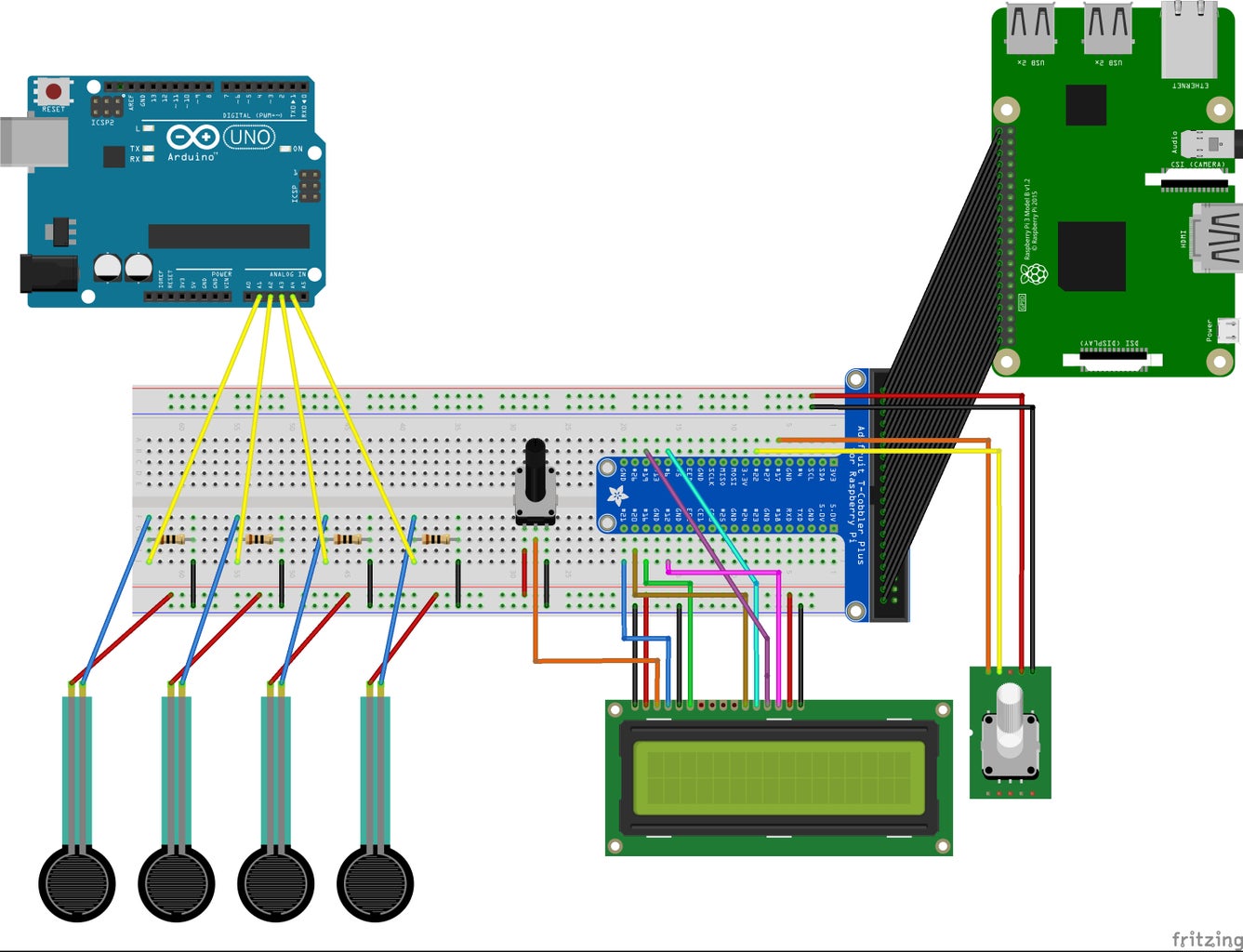
After assembling the board and putting the FSRs, encoder, and screen in place, we wired everything up. You could use 2 breadboards, but we were able to fit everything on one. The picture looks like a mess, but we made a schematic diagram in a free program called Fritzing. Note that you can change what pins you wish to attach everything to, but the diagram corresponds with our code.
Step 8: Finish Coding EVERYTHING
This was the tricky part. As stated in the intro, we could not complete this part. The code is 99% all there, but the one part that did not work was the serial communication from Arduino to Pi. We could send the info easily when we connected the Arduino to the Pi with the USB cable, but the Pi could not do anything except display that info on the screen. We wanted to be able to tell which button was pressed and make that play a specific sound, but the data that was coming through the communication could not be put into a condition statement to test what button was pressed.
Please see the attached code, notes have been commented in the Python code for the Pi. The Arduino code should be 100%.

Step 9: Conclude

Overall, this project was a HUGE learning experience for the two of us and we hope that this write-up can give future students, teachers, or tinkerers some inspiration for their own project and to guide them by learning from our mistakes. Shout out to our awesome robotics professor who helped immensely during our time in class and gave us the opportunity to have a ton of fun and learn a lot in a senior COMP class! Thanks for reading :)


