

Introduction: Python RF Development Kit


First of all, I would like to give a little introduction on how I got into RF stuff and why I am working on this project.
As a computer science student with an affinity to hardware, I started attending some courses that deal with wireless signals and security in wireless communications in October 2018. I quickly started experimenting with RTL-SDR and HackRF software-defined radios and with off-the-shelf Arduino RF modules.
The issue is: SDRs are not portable enough for my purposes (always need to carry a laptop, antennas etc.) and the cheap Arduino RF modules aren't capable enough in terms of signal strength, customisability, frequency ranges and automation.
The CC1101 antennas from Texas Instruments are a great choice for small but capable RF transceivers that are also very cheap. People have built great things with them, like DIY SDRs and stuff like that.
Another thing that I wanted to address with this topic was CircuitPython. It's a new programming language from microcontrollers that I've heard a lot of good stuff about so I wanted to try it. It turned out that I do enjoy it a lot, especially coupled with Adafruit's Feather M4 Express board which I also use in this project. It's very easy to debug as you don't need to compile custom firmwares every time you try a small change in your code, you get a REPL console and your code also stays on the microcontroller itself which means you can carry it around, plug it into various computers and you'll always be able to do changes on the go.
Step 1: Hardware Components
What you'll need to replicate this project:
- Adafruit Feather M4 Express
- 2x Texas Instruments CC1101 Transceiver + Antenna
- Adafruit FeatherWing OLED
- 3.7V LiPo
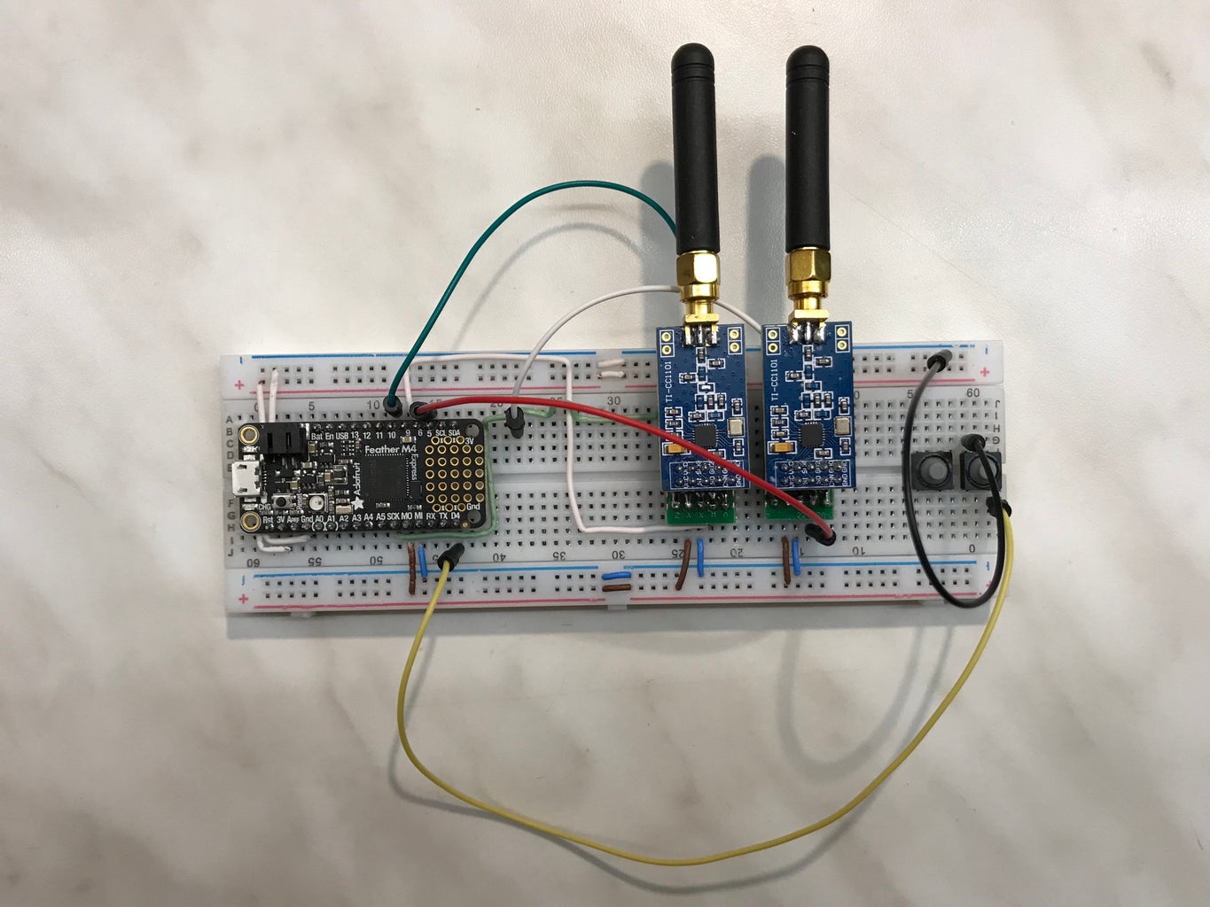
Essentially this is all you need to have a pretty compact and capable RF transceiver, but as you can see in the image it's not going to be very reliable and tidy with all those jumper wires.
So I designed a custom PCB using https://easyeda.com/ and ordered it from JLCPCB.com (very cheap and great quality!) to connect everything together. This also allowed to easily integrate 3 buttons and LEDs for user input and status outputs.
And finally, I 3D printed a little cover for the back of the PCB so it won't short out against anything and sit flat on the table.
If you are new to Electronics and PCB design, I would recommend to check out these Instructables: Basic Electronics, Circuit Board Design Class!
In the attachments you can find the Gerber files for my PCB. If you decide to have it manufactured, you will need a couple of extra components which I personally ordered from LCSC, since they are associated to JLCPCB so they offer to ship everything together which saves a little bit of shipping costs and the components are also just very cheap there. See the BOM for the detailed list. I intentionally chose the large package size of 0805 for the SMD components so everybody can hand-solder them onto the PCB!
Attachments

Step 2: Building the Board


In the first image we can see the PCBs without any "modifications" done - they come like this from the factory. Very clean cuts (no v-groove, completely routed) and nice vias on all of the THT holes.
If you want to use the LEDs you will have to solder them on as well as the SMD resistors. The resistors are usually hidden under the microcontroller but visible in the second picture that shows the completely soldered board. If you don't have a lot of experience with soldering, it could be a bit tricky to solder SMD, but it's kind of optional and all of the core components are THT. I always like to recommend Dave (EEVblog)'s videos and actually watched this one myself: EEVblog #186 - Soldering Tutorial Part 3 - Surface Mount. It's pretty long but worth it if you are new to this stuff!
He mentions this as well, but: take care to solder the resistors and LEDs first, then the buttons second and the headers in the end. This way you can always use the table to push against the component from the bottom and solder from the top (PCB flipped upside down).
After soldering everything on, you can just plug in the Feather M4 and one or two antennas and the hardware is ready! Since we don't solder on these components, we can always take them off the board and use them for another project which is great!
Please note that in the third picture I have the regular, short male headers on the Feather so I couldn't stack the OLED on top. I had to desolder them and add Feather stacking headers. If you want to use the OLED, get the stacking headers right away, honestly :D Desoldering is just a pain.
Step 3: Software
With the hardware done, let's talk about software.
As mentioned in the introduction, the M4 runs Python code, but obviously no library for CC1101 did exist in the Python language. So I did what DIYers do and wrote my own. You can find it here: http://git.io/fhubQ.
It doesn't support everything that the great TI transceivers are capable of but it's enough to send and receive ASK-encoded data on any frequency easily. I was able to communicate with RF-controlled wall sockets as well as with my family's car by using this library.
I may quite probably continue working on it and if you have any questions, feature requests or want to contribute to the development, feel free to contact me!
Step 4: Capabilities and Features
Since I designed this device to use double antennas and the highly configurable TI CC1101 transceivers, you have a ton of possibilities, especially out in the field where you don't want to have to carry anything more than a smartphone-sized device.
You can for example capture signals of communications in the 433MHz band and send them back to your home station with the secondary antenna operating on 868MHz.
Or if you want to study and experiment with reactive jamming, you can have a listening and a jamming antenna that sends its own signals as soon as a transmission is detected, without doing the "traditional method" of trying to switch between RX and TX as fast as possible.
Another very cool thing about the Feather M4 is that it comes with an onboard LiPo charging circuit so you just plug in your battery and are ready to go. In my case, with one antenna in constant RX mode, listening for transmissions and the OLED screen on, the device would run for almost 20 hours on a 1000 mAh LiPo.
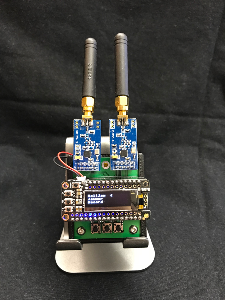
Using the OLED screen - but also possible without it, e.g. using the three status LEDs - you can have multiple programs and select which one you want to run with the buttons on the bottom of the board. I personally even implemented a whole menu with modes to choose from and a frequency setting view etc.
It might even come in hand for some home automation! Like I mentioned, I have been able to communicate with power outlets successfully (capture the original signals once and replay them whenever you need it) and if you do a little bit of research on the Internet you will quickly find how many devices also operate on these frequencies with never-changing codes. Even some garages' codes could be recorded and saved with this device and then used whenever you need to open or close your garage. So this can become a universal remote for all of your RF devices!
I personally replicated the RollJam attack with this device as well, but won't release the code since jamming is illegal in most places so if you attempt anything like this, consult your local laws ;-)
Since the board shows up as a USB disk when you plug it in and CircuitPython offers such a feature, you can also have the device record RF transmissions and save the demodulated data (oh yes, the transceivers do this automatically!) to a text file which you can later copy to your PC and analyse for science purposes like reverse engineering of transmissions.
Step 5: Final Result
Any feedback, suggestions and contributions to this project are welcome and feel free to ask questions if you have any!
Happy Hacking,
Dave

Participated in the
PCB Contest


