

Introduction: QCTP for Taig Lathe


When I acquired the Taig Lathe last year, one of the first modifications I made was an adjustable tool post (see Instructable). This tool post serves me very well and I am quite happy with it. However, everytime I need a different tool bit I have to remove the installed bit and reset the height for the replacement. If the job is one involving many and frequent tool changes, this can be quite tedious. One solution is to make several similar tool posts with different tool-bits installed, and swap tool posts when necessary. Of course, a quick change tool post (QCTP) is a more elegant and handy solution. I looked at some ready made QCTP's on the market as well as several DIY examples. I decide to design and make my own set.
A QCTP is basically a set of tool holders which can be easily dropped and secured onto a base affixed to the cross side, without having to make any adjustments, and used immediately on a job. This is intended to save time and effort. It therefore follows that the QCTP holders must be simple to adjust, and can be swapped with one another with minimum effort and tools.
This Instructable sets out my solution, the design and fabrication of a prototype QCTP and its base.
A number of steps are required to make the different parts. I find it challenging to write out the process in detail. I’ll omit simple operations and concentrate on those steps which are critical. It is not advisable to step out of sequence because some steps rely on the completion of other earlier ones. Consult the drawings provided as necessary.
For the sake of clarity, the following terminology is used:
Axle – steel pillar attached to the Base
Base – unit secured onto the cross-slide with an Axle accepting QCTPs
Cap-screw - #10-32 hex cap screw of various lengths
Cam-rod – eccentric rod which moves the Shoe up and down to lock and unlock the Base
Grub-screw - #10-32 recessed hex head set screw, ¼” long
Handle – bar attached to an eccentric rod which moves the Plunger in or out
Height-adjuster – long screw which adjusts the height of the tool-bit in the QCTP
Plunger – contoured plug used to lock the QCTP onto the Base
QCTP – interchangeable tool holder which can be swapped in easily and quickly
Shoe – part inserted into a T-slot in the cross-slide to secure the Base
Metric units are used throughout this Instructable except where it is necessary to conform to the standard #10-32 imperial screw size of the Taig lathe.
Step 1: Design and Materials


My design requires firstly making a sturdy Axle which stands on a substantial Base, which in turn can be attached securely onto the cross-slide at any position. A 15 mm diameter steel pillar about 43 mm long is fused, either by silver brazing or silver soldering, onto a 36 mm diameter 11 mm thick steel disk. This is bored centrally at the bottom with a 12 mm diameter recess. This recess houses a Shoe which acts as a lock. The Shoe slides into one of the T-slots on the cross slide. The Shoe is elongated with the long edge aligned with the T-slot. This makes it easy to insert and set up quickly, as well as to distribute the locking pressure over a larger area. The Shoe as well as the Base are drilled accross with an 8 mm hole. A Cam-rod with a hex screw head is inserted into this hole. When the Cam-rod is turned, the Shoe moves up or down to lock or release the Base on the cross slide.
A number of QCTPs can be made to hold different tool bits with different shank thicknesses and/or different configurations. These may slightly differ in layout and size but all have a common and identical central hole which slips onto the Base. Each QCTP has a Height-adjuster and a built-in Handle. The Handle secures or releases the QCTP from the Pedestal with a simple twist. Each QCTP is about 36 x 38 x 28 mm big but may differ from one to another. Aluminium alloy is used for the body and mild steel for the Plunger. For a small lathe like the Taig, this material is sufficiently strong for most purposes.
The ball-tipped part of the Handle is designed and made separately and will be covered in another Instructable.
The following materials are required.
For the Base,
steel plate, about 40mm square, 12.5 mm thick (say half inch thick)
steel rod, 16mm diameter, 55 mm long
steel rod, 16mm diameter, ..mm long
steel rod, 8mm diameter, 50mm long
Cap screw, ¼” long
Phillips screw #10-32, ¼” long
For the prototype QCTP
aluminium alloy Body about 30 x 40 x 50 mm
Cap-screw 5/8” long, 3 pieces (for securing tool bits)
Cap-screw, 1½” or 1¾” long (for tool height adjustment)
Grub-screw, point head
Grub-screw, cup head
steel rod 12mm diameter, about 30mm long
steel rod 8mm diameter, about 35mm long
ball tipped handle bar (made separately)
Step 2: Make the Fixed Base


Making the lockable Base is straight forward.
First, turn the 16mm diameter steel rod into a 15mm axle accurately.
Drill a 15mm hole in the centre of the steel plate and insert the steel axle into it. Braze or solder the two parts together. The steel plate becomes a flange on the axle.
Putting the axle into the chuck, turn the brazed unit together and square up both the top and bottom side of the steel flange. This removes some material, and in my case, the resulting thickness is reduced from about 12.5mm to 11mm. As long as it is not thiner than 11mm it does not really matter. The steel plate is then turned into a 36mm disc as an an attached flange.
Drill a 5mm diameter hole from the rim of this flange diametrially through to the other side. Widen this hole to 8mm, either with a drill or an endmill, and stop at a depth of 30mm. Now do the same from the other end, but stop at 5mm. This operation results in a stopped hole with a 1mm thick perforated barrier between the two 8mm sections.
Drill or mill a 12mm diameter cylindrical recess in the underside of the Pedestal, about 25-30mm deep. This provides room for the Shoe.
Step 3: Make the Cam-rod, Shoe and Assemble the Base


The Base is pressed against and locked onto the cross-slide by the Shoe inserted in a T-slot. This is achieved with a cam actuated by the Cam-rod. The Cam-rod has an eccentric section which is 7mm in diameter offset from the 8mm rod centre by 1 mm.
To help machine this, I first make an offset holder to help turn the eccentric section of Cam-rod.
I take a 12mm rod 50mm long, and drill and mill an 8mm blind hole, 30mm deep, offset by 1mm from its centre from one end. I tap two #10-32 holes on the perimeter of the rod, spaced about 60° about 15mm from the open end of the rod (see drawing).
I insert an 8mm rod (to be used as the cam-rod) into this offset holder and lock it securely with two #10 grub screws inserted from the side of the jig. The jig is then secured into the chuck. The rod rotates off centre and an eccentric section is turned until it is about 1mm thinner on one side (see drawing).
Drill and tap #10-32 at both ends of the rod, about 6mm deep. Screw a Cap-screw into one end. If it does not screw in completely, part of the thread can be ground off to fit. Secure in place with solder.
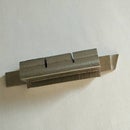
Make the Shoe
Take a piece of 16mm rod and cut it to 23.5mm. This length is not critical and may be slightly more or less. For a length of 20.5mm, turn down to 12mm diameter. Mill down two sides at the wider end until the two parallel sides measure 12mm. Measure 3mm from this end of the rod and mill slots on both sides until the thickness measure 4mm apart. Drill and mill an 8mm hole, at right angles to the long edge of the Shoe, with centre at 14mm from the bottom (see drawing).
Assemble the Base
Insert the Shoe into the recess in the underside of the Base. Insert the Cam-rod into the stopped hole in the flange, through the hole in the Shoe. Hold the Cam-rod in place with a Phillips #10-32x¼” screw in the tapped hole at the open end of the cam-rod.
Using a hex key inserted in the capped end, make sure that the Shoe moves in an out of the Pedestal bottom smoothly.
Step 4: Make the Prototype QCTP


Step 4.1:
Prepare an aluminium blank slightly larger than 28mm x 36mm x 44mm in size. Securing it in the 4-jaw chuck, all six faces are squared on the lathe.
Step 4.2
Mark a centre line along length of the blank. Measuring from one end and along this line mark the centres for a number of holes:
4.5mm tool-bit securing screw hole, centre of 3
17.5mm Axle hole
33mm Handle hole
39mm tapped #10-32 hole for screw which temporary secures the Plunger for drilling
on centre height of tail end of the blank, hole for Plunger
Mark two centres, 4.5mm from front end and from each side, for the two other tool-bit securing screws.
Step 4.3
Drill hole for Plunger, 12mm in diameter.
Step 4.4
Turn Plunger from a piece of steel rod, 12mm x 30mm. Test smooth fit with hole already drilled.
Step 4.5
Drill temporary hole and tap #10-32 through to reach into Plunger hole.
Step 4.6
Insert Plunger into hole and hold in place with a Grub-screw in the temporary screw-hole. The Plunger will be secured here while the Axle hole is bored.
Step 4.7
Insert the Plunger and secure onto the blank with a Grub-screw. Drill and bore Axle hole to 15mm in diameter. Test for snug but smooth fit with the Axle. This operation will shape the head of the Plunger which conforms to the diameter of the Axle, resulting in a tight grip when the Handle is engaged.
Step 4.8
Loosen and slide the Plunger inward towards the Axle by about 0.5mm and again secure it temporarily with a Grub-screw. Drill 8mm hole through the aluminium blank and the Plunger. Drill hole for a Grub-screw to engage the retaining slot on the eccentric shaft of the Handle.
Step 4.9
Drill and tap retaining hole for securing tool-bit.
Step 4.10
Mill tool bit slot, 8 mm deep, 9 mm tall, with bottom of slot at 8 mm from bottom of blank.
Step 4.11
Mark Height-adjuster hole at 24mm from front, 6 mm from side. Drill through and tap #10-32 10mm from bottom. Enlarge top 18mm to 5mm. Drill and tap #10-32 hole from side of body. This accommodates a Grub-screw to lock the Height-adjuster once it is in proper position.
Step 4.12
Make eccentric camshaft. Attach Handle to top of shaft. This will move the Plunger in and out to lock or unlock the Axel from the QCTP.
Step 4.13
The QCTP is assembled. Three Cap-screws are inserted from the top for securing the tool bit. The Plunger is inserted from the back, and the Handle with eccentric shaft is inserted from the top. A Grub-screw is screwed into the hole on the side to retain the Handle from falling or pulling out. The Grub-screw point only engages the recess in the shaft and will not lock it tight, allowing the Handle to rotate freely. Screw in the Height-adjuster and its retaining Grub-screw.
Step 5: Setup and Testing


The Base is attached to the cross-slide by sliding the Shoe into one of the T-slots. By twisting the Cam-rod the Shoe is pressed tightly onto the cross-slide and locks the Base in place.
A suitable tool-bit is held in the tool bit holder. The QCTP is dropped onto the Axle. Loosening the Grub-screw, the Height-adjuster is turned with a hex key and moved up or down until the proper tool height is achieved. It is then secured by tightening the Grub-screw.
The QCTP can be rotated on the Axle to any position. In normal use, the tool-bit is placed at right angles to the cross-slide. By twisting the Handle clockwise by about a quarter to half a turn, the Plunger is jammed tightly against the Axle, locking the QCTP tightly into position on the Base.
This setup is found to be very rigid and I have no trouble test turning a few scrap steel rods of various diameters with it.
I have made two QCTPs so far. The Base took me one day and the prototype QCTP two days to make. The additional QCTP took a day only.
The total cost of this project is negligible.
Over time, I have in mind making more, one for each of the following tool bits:
Right and left hand regular turning tool, 6mm shank
Right and left hand chamfering tool, 6mm shank
Round nose tool, 6mm shank
Boring bar, 6mm shank, etc.
8mm shank bits etc.


