

Introduction: R2D2


The purpose of this Instructable is to provide the reader with a guideline on how I approached building the R2D2 robot. My R2D2 has the following features:
- Dome Rotation
- Projection
- Front and Rear PSI LED’s
- Front and Rear Logic Boards
- LED Holoprojectors
- Audio
- Wireless Ethernet communication to an existing Lost in Space robot
The R2D2 is stationary and does not have motorization for the leg.
Wiring schematics and movies of the R2D2 in action are below.


Step 1: R2D2 Unfinished Shell & Components

Step 2: Dome Bump / Dome Top Pushbuttons


Step 3: Projector

Step 4: Wireless Ethernet

Step 5: Triggerable Digital Video Player

Step 6: Speakers

Step 7: PLC (Programmable Logic Controller)

Step 8: Dome Rotation Stepper Drive & Motor

Step 9: Stepper Drive Motor Hub

Step 10: Lazy Susan Bearing

Step 11: Lazy Susan Gear

Step 12: Connectors

Step 13: Power Entry

Step 14: Power Supply

Step 15: Relays

Step 16: Acrylic Cabochons and Spheres

Step 17: Stepper Drive/Motor
The dome rotation is controlled via a stepper motor connected to a stepper drive. The stepper drive is an AutomationDirect STP-DRV-4850 that is connected to an AutomationDirect STP-MTR-34066 stepper motor.
The stepper drive is connected to the Allen-Bradley MicroLogix 1400 PLC via a serial cable that comes with the stepper drive. The PLC sends commands to the stepper drive such as position, velocity, accel, and decel. I discovered that the PLC will not always communicate to the stepper drive after a PLC power up was initiated but it would always talk via the software tool for the drive. To figure this out, I connected the drive to the software tool and monitored the communications between the software and the drive. What I discovered is that there a few undocumented commands that must be initially sent that make the communication work every time. The following text commands must be sent one time during the initial communication between the drive and the PLC.
- QT
- HRCM
- SK
- CM21
The stepper drive requires a power supply to provide power to the drive and the motor circuit. Since I am using the STP-MTR-34066 stepper motor, the PSB24-120 power supply was utilized that you can also be purchased from AutomationDirect.com. To reduce current when the motor is not turning and to allow manual positioning of the dome before a sequence starts, I have configured the motor to have no idle current 2 seconds after the last move.
When a show is started, I set the position to 0 via a software command, this is like a manual home of the dome. Therefore, having the motor current at 0 allows me to physically rotate the dome to the desired start position so the dome can have any home (0) position desired.
Step 18: Dome

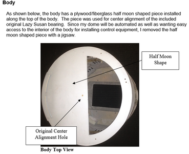
Step 19: Body
Step 20: Rotation


Step 21: Logic Lights


Step 22: PSI LIghts


Step 23: Miscellaneous


Step 24: Paint


Step 25: Control

Step 26: Pushbutton Operation


Participated in the
Fandom Contest


