

Introduction: RC Car Hack With Android and Arduino


In this tutorial, we're going to get your plain old RC to be controlled by Android and give it some extra features
This tutorial has two unique things from other car hacks out there.
1. We're installing a servo for smooth control of the wheels
2. We're using a custom android app that will allow for find tuning speed and direction settings
Besides that we're going to build a horn, we will greatly improve the steering using a servo motor. Cheap RC cars don't have a smooth steering, they usually have a motor that can go left or right and it's pretty hard to control.
Concepts:
- controlling a servo motor
- using a H-bridge
- communication over bluetooth
- using a voltage divider to measure voltage greater than 5V
- PWM (pulse with modulation) technique
If you'll explore the links above you'll find detailed explanations of how these things work.
This is an advanced tutorial, and I think it's for people with some programming experience that want to try something fun, and learn some electronics through practice.
The skills that you'll need:
- tinkering: we'll tear down the old car using a dremel tool and screwdrivers, wire cutters etc
- basic electronic stuff: we'll create a small board using an arduino nano and some soldered components, and then wire them to the car components
- arduino programming: uploading code to an Arduino board using Arduino IDE and a FTDI adapter, making small adjustments to the code
- building an Android app: we'll be fetching code from Bitbucket, build the application and upload it to a mobile device
Step 1: Things Required
Parts:
1. arduino pro mini 16Mhz 5V type (eBay) 2$
2. HC-05 bluetooth module (eBay) 3.3$
3. L298 H-bridge (eBay) 2$
4. buzzer (eBay) < 1$
5. PCB <1$ per piece
6. 2 x 1kOhm rezistor
7. 2 cell LiPo battery 1000mAh
8. L7805CV 5V regulator (eBay) < 1$ per piece
9. male&female pcb connectors < 1$ for what we need
10. XT-60 female LiPo connector (eBay) 1.2$
11. SG90 9G Micro servo motor (eBay)
Tools:
1. Soldering iron for soldering wires to the LiPo connectors
2. Wire cutters
3. Small screwdriver
4. Cutter
5. USB to serial FTDI adapter FT232RL to programm the arduino pro mini
6. Laptop with ArduinoIDE installed to program the arduino
8. An android smartphone
Step 2: Tear Down the Old Car and Install the Servo Motor


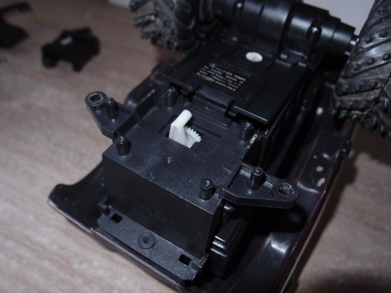


We'll be choosing the RC car and tearing it down, make adjustments etc. I've attached some pictures below for you to see the whole process.
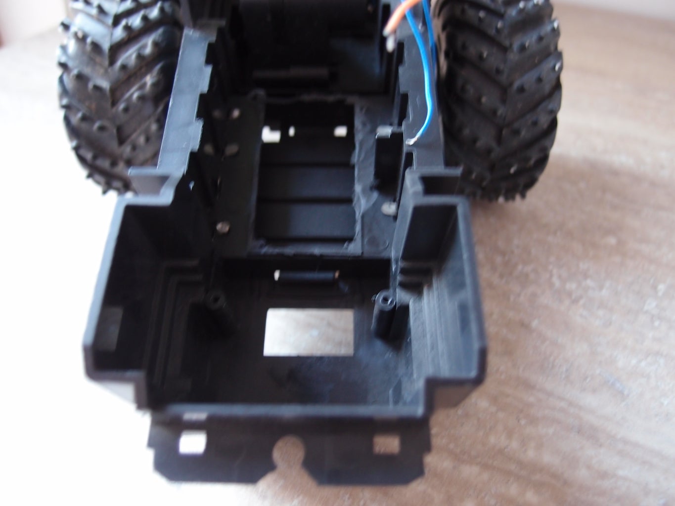
First we'll disassemble the car, and afterwards we'll remove from the interior electronics and useless compartments (like the battery holder and old steering)
The things that we'll have to look out when we're doing this:
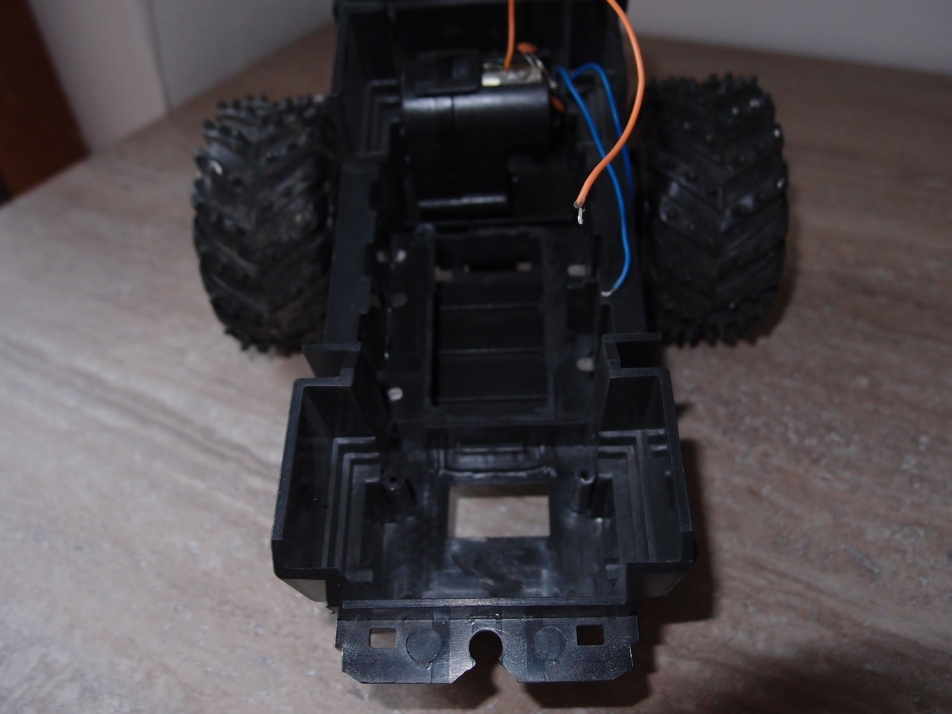
- we have enough room inside the car to install our board with electronic components, a servo, a H-bridge and a LiPo 2S battery
- the servo motor can be installed and it can be adapted to drive the car old steering (if you look in the pictures you'll see how I've achieved this on the particular model of the car)
- we don't damage the car structure, steering and or power train
In the end of this step we should have remove all the car guts, soldered two wires to the car motor, installed a servo motor and connected it to the car steering mechanism.
Step 3: Build the Electronics Board, Install It on the Car


I've attached a fritzing schematic so things will be easier. The custom PCB will contain the Arduino pro mini, a HC-05 bluetooth module, a couple of resistors for the voltage divider, a piezo buzzer and a l7805cv 5V regulator.
The PCB will also have various connectors and wires for easy plugging in. Our board will connect to a power supply, to the car old electric motor via an H-Bridge, and to a servo motor. Also the bluetooth and Arduino pro mini will have custom connectors made out of male & female PCB connectors.
A voltage divider from two identical resistors is present on our PCB so that it reduces voltage under 5 volts for our analog pin to measure. The measurement will be sent to the Android App and will be displayed on the screen.
The car power supply will be a 2 cells LiPo battery with at least 1000 mAh. The battery will directly drive the car motor through PWM. The rest of the electronics will be powered by the same battery but with a l7805cv 5V regulator.
Attachments

Step 4: Uploading the Code on Arduino, and Building the App on Android

The code (get it here) needs to be uploaded to the Arduino pro mini using the USB to serial FTDI adapter FT232RL.
You will need to connect the GND, VCC, Rx, Tx and DTR pin to the Arduino pro mini. Then open the Arduino software select tools/port and whatever port you're using. Then Tools/Board/Arduino Pro or Pro Mini. Then Tools/Board/Processor/ATmega328(5V 16Mhz).
Finally, open the sketch and press upload.
So how does this program works? First it listens to the serial line (a secondary software serial) for incoming transmissions. The message is parsed and interpreted as being a horn command or a motor command (contains speed and direction). After the message is interpreted the commands are transmitted to the motors / horn. Also the sketch regularly polls the A3 analog pin to find out the battery voltage, and it will transmit the data over bluetooth.
Next thing is to clone the Android app repository and build it using Android Studio. The Bitbucket url is: https://bitbucket.org/danionescu/remotecontrollbluetoothrobot
For the Android Studio part there are a lot of tutorials out there like this one: https://www.instructables.com/id/How-To-Create-An-Android-App-With-Android-Studio/
The steps are:
- download and Configure Android Studio
- get the phone in development mode
- import the sources into Android Studio
- build & Install app
Some alternatives to Android Studio would be InteliJ or Eclipse.
Step 5: Running the Application and Troubleshooting the Car


After installing the android app, the first thing to do is pair your bluetooth device using Android. This will involve these steps:
- turn on your car
- go to Android menu / bluetooth
- scan for bluetooth devices
- select your device and pair (enter the code when prompted)
Ok. After this open the Android app, click "List paired" button, click the appropriate bluetooth device from the list and the next screen will be displayed.
The next screen will actually control the car. Using the top horizontal slider you can control the angle of the wheels and using the bottom vertical slider the speed and direction. Also to start / stop the car there is an "On/off" button and the "Custom1" button is the car horn. Below the "custom1" button is a small text with the battery voltage.
Adjustments:
if the car goes back instead of front and vice versa, reverse pins A0 and A1
if you like to modify max / min angle or reverse angle, adjust this code:
void adjustDirection(int direction){
   int newDirection = steeringMiddlePoint + map(direction, 0, 100, -35, 25);
   Serial.println(newDirection);
   steering.write(newDirection);
   delay(15);
}
Step 6: Something for a Future Project
I hope you learned something new in this project, and if you like this idea, you can check this more advanced project with a custom built robot, and an Android app that is more advanced.
The robot is equipped with a video camera, and makes a live streaming through the internet to the app. It can be remotely controlled from anywhere if it has internet.
You will find the arduino code and python backend here along with basic instructions, the android app here. And of course a video demo :)
If you liked the Youtube videos, you can get more by subscribing to my channel here

Participated in the
Invention Challenge 2017


