Introduction: RECYCLED 3d Print Crusher


We had printed and built the compost shredder we’d seen on Thingiverse which had been put up by THYMARK
It worked reasonably well, but there just wasn’t enough “beef” to it for our “wants”. Casting around a few ideas and we came up with a design that has wooden grinding gears. To be sure that the teeth would hold up, I went to a wood specialty shop and asked for the hardest wood they had in stock. I was expecting maple or ash, but he had some Arizona Iron Wood. One look and a quick hefting told me all I needed to know. This stuff is truly like “iron”, tight grain and VERY dense. Perfect for what I wanted. BTW this stuff “ain’t cheap”. One 8 ft. length would do me just fine. We used the original end piece design to hold the bearings. They’re perfect. I had some left over 1” pre-punch square tubing from the first one. I took the grinder apart to get the dimensions of the gear teeth. Traced a gear outline on the wood, outside profile and inside to be able to cut them out. This is where a scroll saw or band saw with a fine blade is perfect. The original design shows four teeth on a side. Like Tim the Tool Man says “More Power” ,,, we went with 6 gears on each side. This is where patience and a steady hand is good to have. The wood is very tough to cut with a scroll saw. I ended up using a band saw to get the outline. Be careful or you’ll break the blade (guilty look) .. To get the inner hole cut, at first I was drilling out a few holes to get the scroll saw blade set up and then follow the lines. After a few times, I got out my Forstner bit and drilled away the majority of the excess material. NOTE HERE ,,,, be very careful drilling, the thing can get away and with those sharp teeth can destroy your fingers. I used a drill vise to hold each one as I was drilling. As I got each hole finished I tested it on the tubing. Any “modification” (ie make larger) was done with my wood rasp to ensure a tight fit on the tubing. I was careful to mark the position of how they fit and in which order they went. We also printed the spacers for the teeth. They slid onto the square tubing quite well. As for the end gears they got printed too, BUT they ended up a whole bunch thicker than the original. Now as for how to turn the teeth. I got some ¾ threaded rod and about a dozen nuts and flat washers. I measured the tubing length to accommodate the teeth and spacers. Putting two nuts on a bit of the threaded rod and inserting it inside the tubing was a bit tricky. You’ll need to grind off some of the end of the nut to make it fit in line with the other nut plus be able to slide inside the tubing. A grinding wheel is handy for this. (WEAR YOUR SAFETY GLASSES) To make sure it wouldn’t slide out I used my MIG welder to fasten the nuts inside of the tubing, To be sure the rod turned inside of the bearings we printed some circles to go over the rod and inside of the bearings. (Think a round shim) The gears have a HEX internal of 1 1/8 to allow the nut to slide in. Because of the thickness of the gear I ground down the thickness of one of the nuts to be able to have two nuts in each gear. I held them in place with a flat washer and two nuts jammed tight to allow freedom of motion yet not slid out of alignment. As for the side panels, we tried printing them. Our printer just wasn’t up to the task (It’s only a 12 x 12) some of the “work” was too close to the edge even with putting it on a diagonal. I decided to get some 3 ½ wide PVC molding at the Local Lowe’s. One 8 foot length was fine. I cut the length to fit on the end panels with a bit of “overage” by about 1/16 th. The drill press did the work of the 3/8 holes to line up with the end panels. Some Helicoil inserts made sure the mounting bolts or studs (which ever you desire) would have a secure bite. As for the angled guides that ride on the spacers, I used my brace and bit to drill out a proper hole (for me this came to 2 1/8 … not wanting to spend the money on a hole saw I did that part by hand) to get the center use your small framing square to make a 45 degree angle on each side and where they cross use a center punch to allow your bit to start. Chop saw to cut the pieces to length. I decided to make the centerline cut a bit off center to allow for the saw blade kerf. (I know that uses up a bit more material but it’s worth it for the finish look.) Once cut to fit I put the blade at an angle to make the cuts that fit over the spacer. NOTE WELL … BE VERY CAREFUL OF YOUR FINGERS WHEN USING THIS SAW. …. UNLESS YOU LIKE THE NICK NAME OF “STUMPY” Once the guides were cut to fit, I placed them inside of the grinder and gave it a few turns to check for freedom of motion. EXCELLENT result. I then marked the inside of the side panel to preset for drilling some mounting screws. HINT once marked out drill a small pilot hole from the inside and counter sink the outside for wood screws. Align and pre drill for each screw. I put my 3/8 drill to it and checked for smoothness of operation. SWEEEET. I did find that I do need a more powerful drill to be able to grind some of the thicker items or I’m gonna have to make a gear reduction set up for the power.
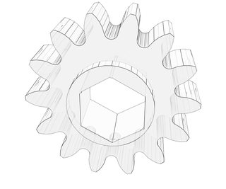
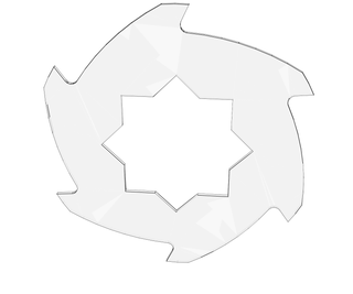
tooth size x and y, veries between 82 and 85mm z 20.0 to20.5mm high 79.5 x,y 27.0 z
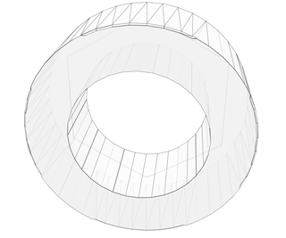
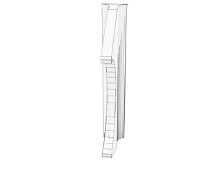
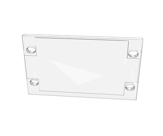
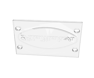
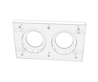
bearing side plate 16mm x 90mm x 160mm
4x ball bearings ( SKF 6006 ZZ or 2RS )
helicoil kit 5/16 or metric equivalent plus bolts
3/4 rod for the center
bunch of 3/4 nuts and washers
8ft length of wood (harder the better)