

Introduction: RFID Controlled Door


This instructable was created in fulfillment of the project requirement of the Makecourse at the University of South Florida (www.makecourse.com)
Fumbling to reach for you keys and then having to find the right one for the corresponding door is usually the first or last headache of the day and it only gets worse if you're carrying something. An RFID door lock can lock and unlock doors with a swipe of a RFID keychain or card. My design uses an Arduino Uno the RFID reader and a servo. The servo that controls the door is being controlled by the micro controller and the arduino is being told when to unlock and lock the door with the RFID reader. When someone swipes the corresponding RFID card in front of the reader, the reader lets the arduino know that the correct card has been read and to then operate the servo, unlocking and locking the door.
Step 1: Parts List
Heres what you'll need:
1 Arduino Uno
1 USB printer cable
10 Jumper Cables
1 SG90 Micro Servo
1 MF522-AN RFID kit (comes with the RFID reader, card and keychain)
1 small breadboard
Optional: For demonstration purposes I 3D printed the blue and orange door lock assembly which can be found at http://www.thingiverse.com/thing:465349
Attachments

Step 2: Setting Up the RFID Reader to Your Arduino
1. Use your breadboard to connect your RFID reader to seven jumper cables that will connect the reader to the arduino.
2. Connect the following RFID reader connections to the arduino pins listed.
MISO to pin 12
SCK to pin 13
SS to pin 10
MOSI to pin 11
GND to GND
3.3V to 3.3V
RST to pin 5
Step 3: Setting Up the Severo to the Arduino
To hook up the servo to your arduino connect the signal cable to pin 9 of the arduino, the black wire to gnd and the red wire to 5V. (See schematic)
Attachments
Step 4: Downloading the Arduino Coding Environment
To write up the code for the arduino you must first download the latest arduino coding environment from http://arduino.cc/en/Main/Software
Attachments
Step 5: Setting Up the Arduino Sketch
I used the code that came with the RFID kit and manipulated it to control the servo.
Use the arduino compiler to upload the following code
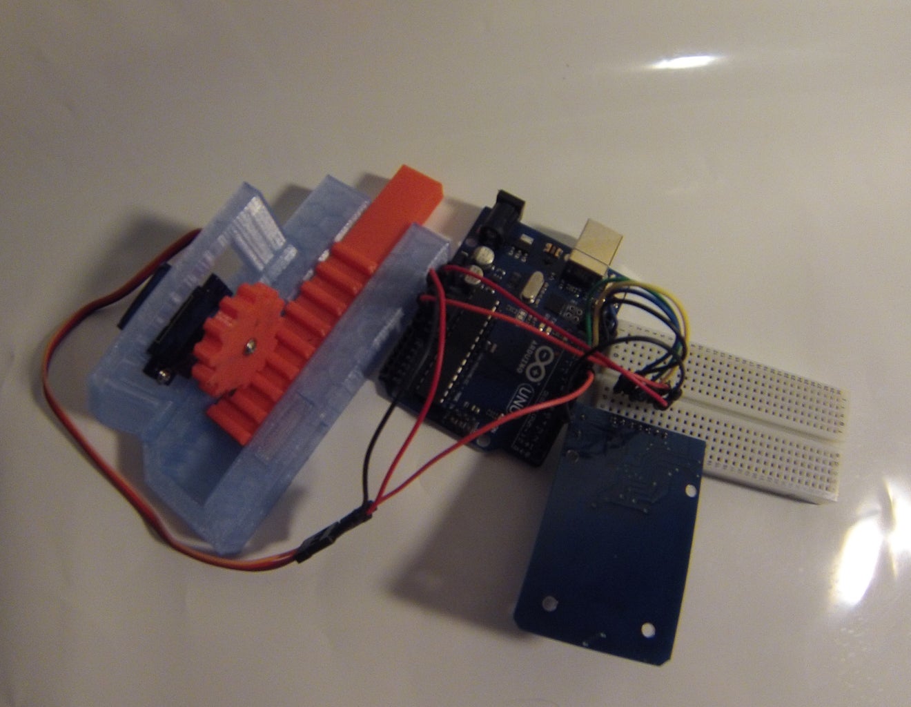
Step 6: Optional 3D Printable Demonstration Lock

To demonstrate that the servo is actually doing its job you can 3D print this demonstration lock that can even be used as a lock. If youd like to incorporate that to your project go to http://www.thingiverse.com/thing:465349 and print it out. In my project I printed the locks stationary parts in see-through blue and all of its moving parts in bright orange. The servo is connected to the large orange gear. When the servo rotates, it spins the gear which slides in the door bolt and then back out again. The action of sliding the door bolt back and forth simulates the door being unlocked and then locked again.
Step 7: Conclusion
There are many other ways to accomplish the same task but this way has seemed to work out even when my hands are full of groceries. Thanks for reading and be sure to follow me as I will be doing more write ups in the near future.
Attachments

Participated in the
3D Design Contest

Participated in the
Formlabs Contest


