

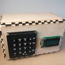
Introduction: RFID Access System


In this instructable I will show you how to make an arduino powered RFID access system that can be easily modified to fit the needs of any project. Before we get in to the build let me explain the technology behind the RFID reader and tags. In case you don't know already RFID stands for Radio Frequency Identification. This technology allows for data to be transferred through electromagnetic fields, but where is that data stored? The data is stored on the RFID chip that is usually powered by electromagnetic induction (think wireless qi charger for a phone or power mat), therefore allowing the card to powered while near a reader. Some cards are powered by battery which is both an advantage and disadvantage, the battery powered cards have much longer range but they also require more space for the battery. All RFID tags have the ability to be read, written to, and rewritten. Now let's turn to the RFID reader, the reader communicates with the arduino over the SPI bus (Serial Peripheral Interface) and is powered by 3.3 volts. The reader I use is a small reader operating at 13.56MHz so the cards can only be detected from a few inches away. So what can we use this technology for? Chances are you already know without realizing it. It is used to unlock doors, collect tolls, monitor livestock, verify your passport, and track your packages.
Step 1: Materials


To complete this project you will need:
- An Ethernet cable
- RFID cards
- SainSmart Mifare RC522 Card Read Antenna RF RFID Reader IC Card Proximity Module
- An Arduino
- Access to a 3D printer
- Filament (preferably black or yellow so paint isn't necessary)
- Access to a Laser Cutter
- 1/4 inch plywood, MDF, or acrylic
- Frosted acrylic
- 1/8 inch plywood, MDF, or acrylic
- A drill and drill bits
- Nuts and bolts
- Red, Yellow, and Green LED's
- Wires
- Protoboard
- Computer with arduino IDE
- USB cable
- Soldering Iron and solder
- Label Maker (optional but useful)
- Pliers
- Wood glue
Step 2: 3D Printing


Let's start out this project by 3D printing the traffic light enclosure. Again, try to print in black or yellow to avoid having to paint the enclosure. If you don't have access to either of these colors try to pick a color as close to white as possible to make the painting process faster and easier. The print took about 14 hours so make sure to start the print at night to avoid waiting and waiting and waiting. I printed the light with two shells at 2% infill with PLA on a makerbot replicator 2. Unfortunately with an extruder based printer this print requires lots of support material which is wasteful but the excess plastic makes good samples for anyone curious about 3D printing. The STL and DWG files are attached somewhere in this step


Step 3: Laser Cutting


We are going to need to make three separate cuts with three different materials. First, we need 1/4 inch material for the electronics enclosure. The enclosure is basically just a box, Next, we will need to laser cut three squares out of frosted or translucent acrylic to diffuse the LED's. Finally, We will need to cut out a backing for the traffic light in 1/8 inch material to secure the components in place and prevent damage and for looks. If your curious I used an epilog laser cutter. The diffuser covers are in the drawing.pdf file, the box is in the Box for light.pdf, and the back of the traffic light is in the file lightback.pdf. The drawings were made in inkscape and for cutting were brought in to corel draw.

Step 4: Box Assembly


Use wood glue to secure three sides of the box together, leave the back side off so the electronics can be inserted later. Drill holes in the back of the case for power, an on off switch, an Ethernet cable for the traffic light, and if you want a cable to reprogram the arduino.
Step 5: Light Assembly


After the light is done printing remove all of the support material, I found it is easiest to remove the material with pliers by breaking it sideways rather than trying to rip it out towards you. If there are any rough spots use a file or sandpaper to clean it up. If the holes to secure the back to the light have plastic in them, rout it out with a drill bit. Now that it looks clean, insert the wall hanger into the slot, it will require some pushing but just keep applying pressure until it slides through, once it has make sure it can rotate. Next, use a hot glue gun to secure the light diffusers in front of the three circles in front of the light. Keep the hot glue gun out, now we need to add the nuts and bolts to hold the back in place. Turn the bolt upside down add a dot of glue on the ridge where the threads end and push the bolt up from inside of the traffic light so that the threads stick out the back and hold it until the glue dries. Repeat this process for the remaining three sides. Put the backing on the light and secure it in place with the nuts
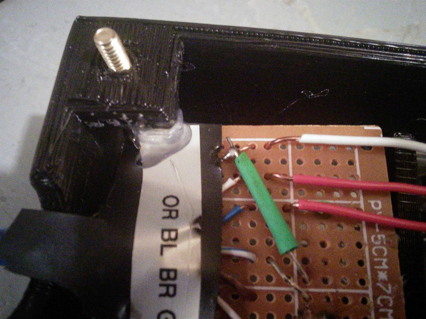
Step 6: Making the PCB


Now we need to get those LED's into the traffic light enclosure. To do this you can either use a very long PCB or split up three pieces of protoboard like I did. Layout the boards so when placed in the light enclosure, they lineup with the diffusers. Now it's time to grab that Ethernet cable. Strip off the leads on both ends of the Ethernet cable and determine which colors should carry ground, red, yellow, and green. Use the label maker to label your choices, it can get hard to remember which is which. Solder all of the Ethernet leads to the bottom most board, and then solder additional wires connecting all of the LED's to a common ground and each color to the positive lead of the corresponding LED.
Step 7: Wiring


Start by creating a common ground between the arduino and the breadboard by hooking the GND pin on the arduino to the blue rail on the breadboard. Next lets wire a piezo with the negative lead going to ground and the positive lead going to pin 8. Now it's tome to hook up that PCB. In the wiring diagram I showed the PCB as three different LEDs to make it easier for people who chose different wires within the Ethernet cable, rather than putting the LEDs on the breadboard, connect the wires of the Ethernet cable that connect to the corresponding LEDs. Once that's done it's time to wire up the RFID reader.
Step 8: More Wiring


To wire the arduino to the RFID reader follow the table below.
NOTE: If you are using the Arduino Mega and you plan to use the RFID library code (next step) do not follow the table, scroll to the end of the step for separate wiring instructions, If you choose use the code without the RFID library you can use the arduino uno wiring diagram
Table format is as follows: Arduino Pin - RFID reader pin
___________Arduino Uno_______________
5 - reset
10 - sda
11 - mosi
12 - miso
13 - sck
3.3V - 3.3V
GND - GND
Table format is as follows: Arduino Pin - RFID reader pin
___________Arduino Mega with RFID library_______________
5 - reset
10 - sda
51 - mosi
50 - miso
52 - sck
3.3V - 3.3V
GND - GND
Step 9: Programming

I have two different versions of my code, one with an RFID library, one without it. The no RFID library code is extremely long and a bit complicated if you are new to arduino but it is done with only the SPI library that is built in to the IDE. I had a very hard time finding documentation of people using this reader but eventually I found a few articles about it and ended up basing my code off of this. If you would prefer to use a library it is available here on github. Once it is downloaded extract the zip file to Documents\Arduino\libraries and rename the rfid-master folder "RFID". Both documents are attached somewhere in this step.
Step 10: Finish the Traffic Light


First, Unscrew the nuts and remove the back. Then, we need to mount the PCB in the traffic light. Place the PCB face down and position it where all four corners are touching one of the four corners were the bolts lock in place. Them apply a dot of hot glue in each corner and support the board until the glue dries. Next run the Ethernet cable out of the bottom arch in the traffic light and glue it down for support. Put the back back on and screw it in place. Now the light is finished
Step 11: Final Assembly


Run all of the wires through the back of the electronics enclosure and put the electronics inside. If needed glue down the Arduino inside the box and secure wires to stable surfaces. If the project is final you can close up the rest of the housing with wood glue, if not leave the back loose so parts can be added, modded, or subtracted. Were almost done.
Step 12: Modify


Make it do something different, here are a list of ideas I though would be good modifications to the project
-Make an RFID lockbox
-Create a virtual currency system with EEPROM or SD storage
-Connect it to the web with an Ethernet shield
-Collect statistics on what cards are being scanned and when
-RFID door lock
-RFID garage opener
If you have any other ideas I would love to hear them in the comments

Participated in the
Tech Contest

Participated in the
Teach It! Contest Sponsored by Dremel

Participated in the
Microcontroller Contest


