

Introduction: RGB Bicycle Rim Lights


After receiving a tech box from Instructables with a ton of amazing goodies and the request to make something with it, I really wanted to make something great with it. The box contained some good tools, but only a few construction materials. I tried (and failed at) a few things, but I ended up making a project around one of the items in the box, an RGB led strip.
The RGB bicycle rim lights are mounted on the rims of a bicycle. Fancy electronics controlling the leds make sure only the right leds (forward facing leds white, backward facing leds red) are on at the right time, giving the illusion the leds are actually stationary. Other fancy animations are also programmed in the controller.
Special thanks to Instructables and Ford for sponsoring me with the materials and tools for making this project.
Step 1: The Concept


First some background information and explanations. If you want to make one yourself or make something based on my rim lights, most information is on this page.
Theory
The concept for bicycle rim lights is fairly simple. There is a ring of leds (rgb leds in my case) facing outward on each side of the rim. When the wheel is spinning, the rim light controller decides what leds need to be on and what leds to be off. The goal is to have the forward facing leds white, and the backward facing leds red. On the frame of the bicycle there is a neodymium magnet and a hall effect sensor on the rim light controller measures when the magnet passes. By counting the time between the sensor sensing the magnet, the rpm of the wheel can be determined. The controller uses this rpm to determine the location of the wheel and what leds need to be on.
The rim light controller consists of a few pieces. First there is the controlling part, a Trinket microcontroller. This controller is cheap and has just the right amount of I/O's for the rim lights (5). It has a battery connector to hook up a LiPo battery, fused with a 2A glass fuse. A voltage divider drops down the battery voltage to safe levels to measure with the Trinket. A hall effect sensor is connected with a mandatory 10K pullup resistor. The remaining 3 pins are used for the 3 signal wires going to the modules.
The led modules have a few crucial parts. The most important component is the 74HC595 shift register. This component switches 8 outputs with only 3 inputs and can be daisy chained, allowing for endless expansion. The other component is the BC547B transistor used to switch the leds on the strip and the resistors necessary for the transistors. There are 6 wires going to the modules, a 5V wire, a 12V wire, a ground wire, STCP wire, SHCP and DS wire.
Formulas
How many modules you will need depends on a few things: The diameter of your wheel, the amount of spokes on your wheel and the length of you led strips. For an example, I will use my own wheel. At the height of where the modules need to be mounted, the diameter is 620mm. The amount of spokes is usually a multiple of 4, and is in my case 36. To get the circumference of the wheel, simply multiply by pi.
circumference = d*pi = 620 * 3.14 = 1946.8mm
The amount of modules I have chosen is 6. This number is in the same table as 36, and so I can have equal spacing. The amount of led strips is double that (12) and the length of each strip is 100mm. With 12 strips, 1200mm will be occupied by led strips. To get the spacing between the led strips, subtract the led strip length from the total circumference and divide by the amount of led strips.
Led strip spacing = circumference - (led strip length * # led strips) / # led strips
Led strip spacing = (1946.8 - (100 * 12)) / 12 = 62.2mm
Step 2: Gathering Materials


First gather the materials. All mentioned materials are for one wheel (2 strips, 1 strip on each side). If you want to make it work for both wheels, multiply everything by 2.
- 2.4m RGB led strip (common anode is preferred)
- 1x Trinket (5V prefered)
- 6x 74HC595 shift register
- 36x BC547B NPN transistor
- 36x 1.8kohm SMD resistors
- 1x Resistor 10k
- 1x Resistor 100k
- 1x Resistor 56k
- 1x Hall effect sensor (I used TLE4905L)
- 1x 2A fuse with holder
- At least one 3 cell Lipo battery (1000-2000mAH)
- 1x neodymium magnet
- 1x vitamin bottle
- Tie-rips
- Clear tape
- Ribbon cable
- Heatshrink
- 3D printing filament
- aluminium strip 10x2mm
- 12x M3x10mm screws
- Double sided PCB stuff (or prefboard)
- (Optionally, candlewax or epoxy)
Tools
- 3D printer
- PCB manufacturing tools (including 0.8mm drill)
- Soldering iron
- Hot glue gun
- drills (2.5mm and 3mm)
- Hacksaw
- Lipo battery charger
Step 3: Etching the Circuits


Download the PDF and print it. Depending on the technique you want to use, you can either print it on photo paper (toner transfer) or clear plastic (UV developing). The etch mask is slightly red shifted for better light blocking, so printing it on a color printer gives even better results. You can find tons of instructions on how to etch your own circuits on Instructables too. If you want to modify the design or export it to some other format, the source file (opened with Fritzing) can be downloaded here: http://ytec3d.com/rgb-rim-lights/
You will need to etch these circuits on double sided PCB's. Mark the protective tape with an up side, make the 6 contact side face that way. Tape over the PCB design printed on regular paper and pre-drill the 2mm (the larger) holes to align both sides. Then use the technique you like to etch both sides of the PCB.
When the PCB is done, drill all holes on the pads with a 0,8mm or 1mm drill.
Attachments

Step 4: 3D Printing Modules


You will need to make the modules on a 3D printer. The modules are optimized for FDM printing. They are completely supportless and take roughly 45 minutes each to print on my Mendel 3D printer at 0,4mm layer thickness. These parts are not optimized for SLS printing (3D printing services) and will be expensive there. Upon request I can redesign the modules for 3D printing services.
In my case I needed to print 6 of these modules for each wheel, 12 in total. Download the Stl files in the attachment or in here: http://ytec3d.com/rgb-rim-lights/
Attachments

Step 5: Soldering RGB Modules


Parts required per module:
1x 74HC595
6x BC547B transistor
6x 1.8K SMD resistor
4x RGB led strip
4x 4 wire lengths of ribbon cable
1x 6 wire long length of ribbon cable
Because the home etched circuits have no through hole plating, some parts will need to be soldered on both sides. Depending on how good you PCB manufacturing tools are, you might need to scrape the copper from between contacts (like I had to). Especially between the led and communication pads, there might be some thin strands of copper left.
- First component to be soldered to the circuit is the 74HC595. The top is on the output side, the square pad is pin 1 of the 74HC595. All bottom pads are soldered and 3 pads on the top are soldered. The 3 pads on the top of the circuit that need to be soldered are: Pin 8, 9 and 13. Make sure the solder goes all the way around the pad.
- The BC547B transistors are next. Place them in the top facing the way showed in the picture. Solder them at the bottom, clip the excess (store them, they are needed again in step 3), and solder the top of the transistors at the legs facing the 74HC595.
- The Via's are next. Because there was no through hole plating, some connections need to be made from the top of the circuit to the bottom. These are all the holes that remain, all of them near the connection pads. Put a piece of the transistor wire through the hole and solder on both sides. This connects the top and bottom pads.
- The SMD resistors are tricky. The are incredibly tiny and hard to handle. First tin one of the two resistor pads. The with a pair of pliers get the resistor close to the tinned pad and heat the solder. Place the resistor in place and let the solder cool. When you are satisfied with resistor's location, solder the other pad to make the connection permanent.
- Next step is to tin the 28 pads on the circuit. This will make soldering wires to them a whole lot easier in the next step.
- Strip the protective cover from the contacts with a knife. Check what side to strip, there are 2 different sides. While it is not terribly important, for sake of consistency, pick one side and stick with it. When the waterproof layer is of, use the knife the carefully scrape clean the contacts.
- Solder the lengths of 4 wire cable to the rgb strips, then to the modules (look at polarity when soldering the strips. It is easiest if you pretin the contacts on the led strip and also pretin the wires on the cable. This will ensure a perfect connection every time.
- The last step is to connect the modules together with 6 wire ribbon cable. Be sure to use long enough bands of cable, you will actually need to cover quite a distance with the cable. Also include the length of wire lost in the holders (around 8cm). It's easier to solve too much cable than it is too little.
Step 6: Assembling RGB Modules


With the led strips done, the modules can be assembled.
- The first thing to do is to cut the aluminium to size. The length of the aluminium has to be 2 * the length of your led strips + 1 * the led strip spacing. Calculate this value and cut 10*2mm aluminium strips to this length.
- Use tape to wrap the aluminium strips. THIS IS IMPORTANT. The glue on the back of the led strips is no insulator, but can leave small shorts. This is easily mistaken for any other technical defect. By wrapping the aluminium in a layer of tape, you will insulate the aluminium and prevent short.
- Drill a 3mm hole in the exact centre of the aluminium strip. Then use a slightly larger drill to clean the bottom of the hole.
- Pre-drill the 3D printed holders with a 2.5mm drill. This way it is easy to screw in the M3 screws.
- Use 2 pliers to carefully bend the aluminium strips. The exact radius needs to be determined at your wheel. Do not bend around the drilled holes, you will overbend there. A short tip: Torque bend in a circle, force bends in a parabola. We want circle, so apply torque, not force.
- Mount one of the aluminium strips to the holder. The other side will be mounted when the module is mounted on the wheel, else the module will not fit.
- Add the circuit to the module. Make the circuit face the same way every time, this way it is easier to orient the RGB strips and make the leds light up in the right order.
- Peel of the protective tape from the back of the led strips and stick them to the aluminium. Only the side with the aluminium strip needs to be added for now.
- The glue on the back of the led strips might not be the best quality. Use some clear tape to tape down either side and the middle of the led strips. This way you can be sure all led strips will stay stuck.
Step 7: Hall Effect Sensor


Hall effect sensor needs to be wired and protected from the environment. The hall effect sensor used it the tle4905l, but there are plenty of alternatives. Just make sure you have a unipolar hall effect sensor. A 20cm piece of 3 pole ribbon cable is soldered to each leg of the hall effect. Use small pieces of heat shrink (added before soldering) to insulate the legs. It is best to have a marked side attached to pin 1 of the hall effect sensor, because all reference points will be covered later.
Last step is to cover the actual sensor. A hall effect can be covered by anything not conductive, so it is going to be sealed using heatshrink. Find a piece big enough to fit over the hall effect, around 2cm long. Use a hot glue gun to put a drop of glue over the hall effect, and while it is still hot, place the heatshrink over the sensor. Now with a lighter, heat the heatshrink and the glue. This will melt the glue while the heatshrink is shrinking, effectively sealing the sensor.
Step 8: The Main Controller


The main controller is the piece of electronics that controls the led strip modules. In it's core it is a Trinket, mounted on a piece of perfboard. I understand that making a perfboard circuit is quite odd, considering that you already need to etch to make the modules, but the controller was still from the first attempt (see step 14). If anyone wants a PCB design for the main controller, please ask and I will design one.
- First use a piece of header to solder the trinket to the prefboard.
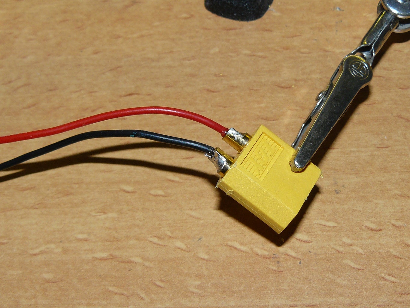
- Wire a battery connector (I used XT60 for mine) and solder the wires to the board. I added the switch later, but between the positive lead and the controller, there should be a switch.
- The fuse protects the battery when the modules short out. This can happen when you drive through water. Lipo's do not like shorts, and might blow up. Use a 2A fuse to protect the battery.
- he hall effect sensor needs a 10k pullup resistor between the 5V pin and the signal pin.
- The voltage divider measures the voltage of the battery and warns the user when the battery is running low. It consists of a 100k resistor and a 56k resistor. The 100k is on the battery side, the 56k is at the ground, and between the 2 is voltage measurement.
- The bottle needs 2 holes, 1 for the wires (4mm) and 1 for the switch (6mm).
- Run the wires of the rim light modules and the hall effect through the 4mm hole and solder the wires to the right pins of the trinket.
- Last step is to stuff everything in the bottle and twist the cap on. You can now test the rim lights. If you did everything right, if you turn it on, the idle animation will looks smooth and go in one direction. One thing that can go wrong is that the general direction is correct, but each module of 2 goes the wrong way. Simply swap the output wire and input wire direction and the animation should go the right way.
Step 9: Firmware
The firmware controls the RGB rim lights. The code was written in the Arduino IDE. Go to http://arduino.cc/ to download the Arduino IDE.
Before you can compile and flash the code, you will also need to follow the guide for the trinket. It requires some additions to the IDE before your computer can communicate with the Trinket. For the guide, go here: https://learn.adafruit.com/introducing-trinket/introduction
With all of these things done, you can open the code. Download it or copy/paste the code below to get started. There are a few things you can tweak to customize your own rim lights:
'OffTime' is the time the sensor needs to be off before the wheel goes into idle.
'AnimationSpeed' is the time between each update of the idle animation. 83ms is the default, which is one revolution of the animation each second (1000ms/12modules = 83.33ms)
'AnimationSlots' is the amount of different colors there are on one rim. In my case there is 5. 2x off (at the start and end), 1x white, 1x yellow and 1x red. Be aware that each animation slot consumes RAM memory and the trinket does not have much of this.
- At the bottom, there is 'LedAnimation[n][m]'.
- n = the slot of the animation slots (0-4). This is the amount of different colors you can have on one rim. You start at 0 (where the sensor and magnet align) and ends at 255 (a few mm before the alignment). No color is also a slot.
- m = the thing being defined. m=0 is the start point of the given color, m=1 is the end point (needs to be higher). m=2 is if the blue color needs to be on (1=yes, 0=no). m=3 is if the red color needs to be on (1=yes, 0=no). m=4 is if the green color needs to be on (1=yes, 0=no).
/*<br>  RGB rim light firmware V1.00

 The firmware used to control the RGB bicycle rim lights. Uses a TLE4905L Hall effect sensor (or other unipolar hall effect sensor)
 to measure the rpm of a bicycle wheel and lights up specific groups of RGB leds to always light up the front white (front wheel)
 and the back red (back wheel) and have special animations if wanted by the user. The RGB modules are daisy chained 74HC595 IC's
 that each drive 2 sets of RGB leds.

 It is configurable for any amount of modules and animations.

 This code is written in the hope that it will be useful, but no garuantees.

 Written by Y. de Haas, latest version written 24-12-2014 (dd-mm-yyyy (like it should be)) More information on <a href="http://Ytec3D.com" rel="nofollow"> http://Ytec3D.com
</a>

 */
//pin layout
const byte LatchPin = 1;
const byte VoltagePin = 2;
const byte ClockPin = 3;
const byte DataPin = 4;
const byte HallSensor = 0;

//configurations
const byte NumOfModules = 6; //The amount of 74HC595 modules daisy chained together
const byte BrightnessStates = 8; //The amount of brighness steps. More is more accurate, but lower frequency
const long OffTime = 2500000; //The amount of time (us) the hall sensor can sense nothing before the wheel registers as not moving
const byte PWMStepTime = 250; //The amount of microseconds each PWM step takes
const byte AnimationSpeed = 83; //in milliseconds (default = 83)

const byte CatchUpSpeed = 20; //the amount of millis before the animation catches up to wheel location by 1/255th of a rotation

const word LowVoltageThreshold = 725; //voltage at which first warning start
const word LowVoltageBlink[2] = {200, 5000}; //on and off intervals for low voltage
const word CritVoltageThreshold = 695; //voltage at which critical warning starts
const word CritVoltageBlink[2] = {200, 1000}; //on and off intervals for low voltage

//Animation information
const byte AnimationSlots = 5; //the amount of colors in the animation (OFF is also a color)
//NumOfAnimations: what animation, AnimationSlots: The amount of defined colors in one animation,
byte LedAnimation[AnimationSlots][5]; //5: (0)start coordinate, (1)end coordinate, (2) blue on, (3) red on, (4)green on

//variables
word WheelLocation = 0;
byte AnimationLocation = 0;
int AnimationLocationOffset = 0, AnimationCurrentOffset = 0;
byte WheelMoving = 0; //states if the wheel is moving or not, needed for startup
byte PWMState = 0;
byte AnimationState = 12;
byte HallHistory = 1;
byte WheelMovementHistory = 0;
byte VoltageBlinkState = 0;

unsigned long WheelHistory = 0, WheelSpinTime = 0;
unsigned long PWMTarget = 0;
unsigned long AnimationTarget = 0;
unsigned long CorrectionTarget = 0;
unsigned long VoltageBlinkTarget = 0;

//LedState[n] states which color each led on each module is in 'BrightnessStates' intervals. LedState 0 is off, Ledstate 'BrightnessStates' is full brightness.
byte LedState[NumOfModules*2][3]; //LedState[n][0]=blue, LedState[n][1]=red and LedState[n][2]=green
boolean PWMLedState[NumOfModules*2][3]; //if leds should be on in relation to PWM

byte TempOutputRegister[NumOfModules];

void setup()
{
  pinMode(LatchPin, OUTPUT);
  pinMode(ClockPin, OUTPUT);
  pinMode(DataPin, OUTPUT);
  pinMode(VoltagePin, INPUT);
  pinMode(HallSensor, INPUT); //warning, inverted, 0 is sensing, 1 is not sensing.
  SetAnimations();
}

void loop()
{
  if (WheelMoving == 0 || WheelMoving == 2) //if the wheel is not moving or in state 2, do the animation
  {
    StationaryAnimation();
    WheelMovementHistory = 0;
  }


//if the hall sensor senses, update wheel states
  if (digitalRead(HallSensor) == 0 && HallHistory == 1)
  {
    HallHistory = 0;
    if (WheelMoving == 0) //if wheel was not moving, go to first revolution
    {
      WheelMoving = 2;
      WheelHistory = micros();
    }
    else if (WheelMoving == 1) //if wheel is in stable motion
    {
      WheelSpinTime = micros() - WheelHistory;
      WheelHistory = micros();

      //determine offset based on current location
      AnimationLocationOffset = AnimationLocationOffset + 255 - WheelLocation;
      if (AnimationLocationOffset < -127)
      {
        AnimationLocationOffset += 255;
      }
      else if (AnimationLocationOffset > 127)
      {
        AnimationLocationOffset -= 255;
      }

      WheelLocation = 0;
    }
    else if (WheelMoving == 2) //if wheel has moved one revolution
    {
      WheelMoving = 1;
      WheelSpinTime = micros() - WheelHistory;
      WheelHistory = micros();
      WheelLocation = 0;
      AnimationLocation = 0;
    }
  }

 //calculate wheel position based on wheel spin time and history
  if (WheelMoving == 1)
  {
    //remap position to 0-255
    float WheelTemp = micros() - WheelHistory;
    WheelTemp = WheelTemp * 255;
    WheelTemp = WheelTemp / WheelSpinTime;
    WheelLocation = int(WheelTemp);
    //check is wheel was moving, if not, match wheel location to animation location
    if (WheelMovementHistory == 0)
    {
      WheelMovementHistory = 1;
      AnimationLocation = WheelLocation;
    }
    AnimationLocation = WheelLocation; //temporary link wheel location to animation location


    //update led animation states based on animation location
    long TempAnimationLocation;
    for (byte i=0; i < NumOfModules*2; i++) //for the amount of leds
    {
      TempAnimationLocation = 256 * i;
      TempAnimationLocation = TempAnimationLocation / (NumOfModules*2);
      TempAnimationLocation = AnimationLocation + TempAnimationLocation;
      TempAnimationLocation = TempAnimationLocation % 256;
      //TempAnimationLocation = i*21;

      //recalculate the location based on what module is on
      for (byte j=0; j < AnimationSlots; j++) //for the amount of color on the animations
      {
        if (TempAnimationLocation >= LedAnimation[j][0] && TempAnimationLocation < LedAnimation[j][1])
        {
          LedState[i][0] = LedAnimation[j][2];
          LedState[i][1] = LedAnimation[j][3];
          LedState[i][2] = LedAnimation[j][4];
        }
      }
    }
  }

  //Reset Hall history to 1 if the sensor no longer senses.
  if (digitalRead(HallSensor) == 1 && HallHistory == 0)
  {
    HallHistory = 1;
  }

  //overrule led states for half of the leds if voltage is low or critical
  if (analogRead(1) < LowVoltageThreshold)
  {
    word TempVoltage = analogRead(1);
    if (millis() > VoltageBlinkTarget)
    {
      //set new target
      if (TempVoltage > CritVoltageThreshold && TempVoltage < LowVoltageThreshold)
      {
          VoltageBlinkTarget = millis() + LowVoltageBlink[VoltageBlinkState];
      }
      else if (TempVoltage < CritVoltageThreshold)
      {
        VoltageBlinkTarget = millis() + CritVoltageBlink[VoltageBlinkState];
      }

      //set new blink state
      if (VoltageBlinkState == 1)
      {
        VoltageBlinkState = 0;
      }
      else
      {
        VoltageBlinkState = 1;
      }
    }

    if (VoltageBlinkState == 1)
    {
      for (byte i=0; i < NumOfModules*2; i++)
      {
        LedState[i][0] = 0;
        LedState[i][1] = 1;
        LedState[i][2] = 0;
      }
    }
  }

  UpdateLeds();

  //Go to WheelMoving = 0 if the wheel is stationary for too long
  if (WheelMoving == 1 || WheelMoving == 2)
  {
    if (micros() > WheelHistory + OffTime)
    {
      WheelMoving = 0;
    }
  }
}

//Functions ----------------------------------------------------------------------------------------------------------------------
void UpdateLeds()
{
  bitWrite(TempOutputRegister[0], 2, LedState[1][0]);
  bitWrite(TempOutputRegister[0], 3, LedState[1][1]);
  bitWrite(TempOutputRegister[0], 4, LedState[1][2]);
  bitWrite(TempOutputRegister[0], 5, LedState[0][0]);
  bitWrite(TempOutputRegister[0], 6, LedState[0][1]);
  bitWrite(TempOutputRegister[0], 7, LedState[0][2]);

  bitWrite(TempOutputRegister[1], 2, LedState[3][0]);
  bitWrite(TempOutputRegister[1], 3, LedState[3][1]);
  bitWrite(TempOutputRegister[1], 4, LedState[3][2]);
  bitWrite(TempOutputRegister[1], 5, LedState[2][0]);
  bitWrite(TempOutputRegister[1], 6, LedState[2][1]);
  bitWrite(TempOutputRegister[1], 7, LedState[2][2]);

  bitWrite(TempOutputRegister[2], 2, LedState[5][0]);
  bitWrite(TempOutputRegister[2], 3, LedState[5][1]);
  bitWrite(TempOutputRegister[2], 4, LedState[5][2]);
  bitWrite(TempOutputRegister[2], 5, LedState[4][0]);
  bitWrite(TempOutputRegister[2], 6, LedState[4][1]);
  bitWrite(TempOutputRegister[2], 7, LedState[4][2]);

  bitWrite(TempOutputRegister[3], 2, LedState[7][0]);
  bitWrite(TempOutputRegister[3], 3, LedState[7][1]);
  bitWrite(TempOutputRegister[3], 4, LedState[7][2]);
  bitWrite(TempOutputRegister[3], 5, LedState[6][0]);
  bitWrite(TempOutputRegister[3], 6, LedState[6][1]);
  bitWrite(TempOutputRegister[3], 7, LedState[6][2]);

  bitWrite(TempOutputRegister[4], 2, LedState[9][0]);
  bitWrite(TempOutputRegister[4], 3, LedState[9][1]);
  bitWrite(TempOutputRegister[4], 4, LedState[9][2]);
  bitWrite(TempOutputRegister[4], 5, LedState[8][0]);
  bitWrite(TempOutputRegister[4], 6, LedState[8][1]);
  bitWrite(TempOutputRegister[4], 7, LedState[8][2]);

  bitWrite(TempOutputRegister[5], 2, LedState[11][0]);
  bitWrite(TempOutputRegister[5], 3, LedState[11][1]);
  bitWrite(TempOutputRegister[5], 4, LedState[11][2]);
  bitWrite(TempOutputRegister[5], 5, LedState[10][0]);
  bitWrite(TempOutputRegister[5], 6, LedState[10][1]);
  bitWrite(TempOutputRegister[5], 7, LedState[10][2]);

  //set all led states to registers
  digitalWrite(LatchPin, LOW);
  shiftOut(DataPin, ClockPin, MSBFIRST, TempOutputRegister[0]);
  shiftOut(DataPin, ClockPin, MSBFIRST, TempOutputRegister[1]);
  shiftOut(DataPin, ClockPin, MSBFIRST, TempOutputRegister[2]);
  shiftOut(DataPin, ClockPin, MSBFIRST, TempOutputRegister[3]);
  shiftOut(DataPin, ClockPin, MSBFIRST, TempOutputRegister[4]);
  shiftOut(DataPin, ClockPin, MSBFIRST, TempOutputRegister[5]);
  digitalWrite(LatchPin, HIGH);
}

void StationaryAnimation()
{
  if (millis() > AnimationTarget)
  {
    //set next target and update state
    AnimationTarget = millis() + AnimationSpeed;
    AnimationState ++;
    if (AnimationState > 11)
    {
      AnimationState = 0;
    }

    //animation
    for (int i = 0; i<12; i++)
    {
      byte temp = i;
      temp += AnimationState;
      if (temp > 11)
      {
        temp -= 12;
      }
      if (temp >= 0 && temp < 1)
      {
        LedState[i][0] = 0;
        LedState[i][1] = 1;
        LedState[i][2] = 0;
      }
      else if (temp >= 2 && temp < 4)
      {
        LedState[i][0] = 0;
        LedState[i][1] = 1;
        LedState[i][2] = 1;
      }
      else if (temp >= 4 && temp < 6)
      {
        LedState[i][0] = 0;
        LedState[i][1] = 0;
        LedState[i][2] = 1;
      }
      else if (temp >= 6 && temp < 8)
      {
        LedState[i][0] = 1;
        LedState[i][1] = 0;
        LedState[i][2] = 1;
      }
      else if (temp >= 8 && temp < 10)
      {
        LedState[i][0] = 1;
        LedState[i][1] = 0;
        LedState[i][2] = 0;
      }
      else if (temp >= 10 && temp < 12)
      {
        LedState[i][0] = 1;
        LedState[i][1] = 1;
        LedState[i][2] = 0;
      }
    }
  }
}<br>
void SetAnimations()
{
  //uncomment the animation you want to show and comment the other animation
  //rear wheel animation
  /*
  LedAnimation[0][0] = 60; //start point
  LedAnimation[0][1] = 100; //end point
  LedAnimation[0][2] = 1; //blue led
  LedAnimation[0][3] = 1; //red led
  LedAnimation[0][4] = 1; //green led

  LedAnimation[1][0] = 100; //start point
  LedAnimation[1][1] = 140; //end point
  LedAnimation[1][2] = 0; //blue led
  LedAnimation[1][3] = 1; //red led
  LedAnimation[1][4] = 1; //green led

  LedAnimation[2][0] = 140; //start point
  LedAnimation[2][1] = 200; //end point
  LedAnimation[2][2] = 0; //blue led
  LedAnimation[2][3] = 1; //red led
  LedAnimation[2][4] = 0; //green led

  LedAnimation[3][0] = 200; //start point
  LedAnimation[3][1] = 255; //end point
  LedAnimation[3][2] = 0; //blue led
  LedAnimation[3][3] = 0; //red led
  LedAnimation[3][4] = 0; //green led

  LedAnimation[4][0] = 0; //start point
  LedAnimation[4][1] = 60; //end point
  LedAnimation[4][2] = 0; //blue led
  LedAnimation[4][3] = 0; //red led
  LedAnimation[4][4] = 0; //green led
  */

  //front wheel animation

  LedAnimation[0][0] = 40; //start point
  LedAnimation[0][1] = 120; //end point
  LedAnimation[0][2] = 1; //blue led
  LedAnimation[0][3] = 1; //red led
  LedAnimation[0][4] = 1; //green led

  LedAnimation[1][0] = 120; //start point
  LedAnimation[1][1] = 150; //end point
  LedAnimation[1][2] = 0; //blue led
  LedAnimation[1][3] = 1; //red led
  LedAnimation[1][4] = 1; //green led

  LedAnimation[2][0] = 150; //start point
  LedAnimation[2][1] = 190; //end point
  LedAnimation[2][2] = 0; //blue led
  LedAnimation[2][3] = 1; //red led
  LedAnimation[2][4] = 0; //green led

  LedAnimation[3][0] = 190; //start point
  LedAnimation[3][1] = 255; //end point
  LedAnimation[3][2] = 0; //blue led
  LedAnimation[3][3] = 0; //red led
  LedAnimation[3][4] = 0; //green led

  LedAnimation[4][0] = 0; //start point
  LedAnimation[4][1] = 40; //end point
  LedAnimation[4][2] = 0; //blue led
  LedAnimation[4][3] = 0; //red led
  LedAnimation[4][4] = 0; //green led

}
Attachments

Step 10: Adding It to the Bicycle


Mount the modules on the spokes of your bicycle. My bike had 36 spokes and I have 6 modules, so I need to mount a module every 6 spokes. The modules should have 1 mounted aluminium strip, and 1 unmounted strip. All of the bottom (closest to the hub) all modules need to be clamped down. Depending on how many modules you have, not all top tie rips can be used. If that is the case, use a larger tie rip to clamp the module on the opposing spoke. From start to end, the modules should be mounted in the opposite direction of the the wheel rotation.
When you have mounted the modules, you can attach the other led strip on the other side of the rim.
Use some large tie rips to get the bottle with the controller and battery in place. Before you make anything permanent test if the wheel can make a full revolution without the bottle hitting anything. When you are happy with the bottle's location, tie rip it in place.
The hall effect sensor needs to be glued on one of the modules (preferably the one closest to the controller). Used a dab of hot glue to glue the sensor halfway on a 3D printed module.
Some pieces, like the bottle holding the controller and the battery, fit quite snug and need to stay where they are. Use some more hot glue on the places where the tie rips meet the spokes to set them in place.
With everything mounted, used some more tie rips to keep the wires on the spokes. If you skip this step, the wires might snag on your frame and you will rip of your rim lights.
Now my bicycle had a small clamp for the wires of the dynamo that was in the way. I first removed the dynamo, scored the clamp with a Dremel and used a pair of pliers to bend it out of the way. Your bike may also have obstructions to the system, like breaks and clamps.
The magnet holders are made with a piece of scrap aluminium (10x2mm). The piece of aluminium was bent so the spacing between the frame and the hall effect is right (around 3mm). Test the directions the magnets need to face by running them past the hall effect. If the animation start,s you have the right side. Tape the magnets to one side of the strip, and use tie rips to mount the holder to the frame of the bicycle.
Step 11: Using It
Using the rim lights is fairly straight forward.
- Turn on the controller, and the lights will go on (somewhat randomly).
- Wait a few seconds and the controller will go into idle mode.
- When you start cycling, it will take the rim lights 2 revolutions of the wheel to determine location and speed.
- After the 2 revolutions the animation will start.
- When you rapidly accelerate or decelerate, you can see the animation moving on the wheel. This is the rim lights not yet knowing where they are.
- After you have stopped and not moving for 2,5 seconds, the rim light will go into idle again.
Step 12: Additional Step, Cast in the Circuits
The led strip modules are designed in such a way that the circuits can be cast in. This way the electronics are completely waterproof. The casting can be done with a few things, but the 2 things I can think of are wax (such as candle wax) or epoxy (permanent).
This step has not been tried out yet, There were deadlines. I will try the casting later and will update the instructable when I have.
Step 13: Future Improvements


No project is complete without an evaluation of what can be done better. This project especially still has a lot of improvements. I may do some of the improvements, but some require me to completely start over, and for now I think I am done making bicycle lighting. Upon request I can revisit this project and make it easier to make and more practical, but for now, the way it is works fine.
- Better power supply: A lipo battery is far from ideal in this situation. It is hard to charge and can provide way more power than necessary (dangerous in an environment with lots of water). In the future I would probably design something that is a bit more stable and a bit easier to charge. Maybe I will even completely remove the power supply from the wheel and use some clever way of getting the power to the wheel.
- Wheel unbalance: The battery sits halfway between the rim and the shaft. It ways over 100 grams (3 ounces) and spins at 300rpm max. This unbalance is easy to ignore, but is most certainly there. It would be wise to move the controller and battery closer to the shaft, or even better, remove the battery from the controller altogether. This way, the system will be more balanced.
- Less leds: 2,4 meters of led strip per wheel is overkill. It produces more light than necessary and consumes a lot of power. If I were to do this again, I would most definitely use only 5cm strips of led, instead of the 10cm I used. I wanted to use up the entire spool of led strip because I had no other use for it anyway, but in retrospect 5cm would have been plenty.
Step 14: The Old Attempt


The first attempt was to dead bug a 595 and put everything in a tube. This worked in theory for 1 module, but I would have to make 24 of them, and honestly, that would have never happened. The circuits were simply too fragile. and the tube wouldn't have fit on the rim anyway.
The attempt described here was my second attempt and my first serious attempt. The idea was that I would make 6 hand soldered modules per wheel. The modules worked just fine, though it took me over an hour to make just one module. The modules were going to be mounted on bent aluminium rings mounted on either side of the wheel. The modules were sealed using conformal coating. This was not going to make the circuits completely water tight, but was some barrier to water. This was far from ideal, but with half the wheel already done, it had to do.
I had messed around with the idea of designing and making a PCB, but left the idea because I wanted to make it as maker friendly as possible. Not everyone has PCB manufacturing tools (or a 3D printer). When the first few modules were done, there was no going back without loss.
All was well until I mounted the led strips to the aluminium ring. Modules mysteriously stopped working, or started overheating. In retrospect this was due to the led strips shorting out on the aluminium, but at the time I though the the stress on the wires had caused some of the modules to fail. I already was somewhat done with the concept and at that point decided that it would be easier to start over with PCB's than to make another fragile set for the other wheel. This concept was dropped and it was replaced with the concept you see described in the rest of the instructable.

Participated in the
Make it Glow!

Participated in the
3D Design Contest


