

Introduction: RGB LED - Arduino


Let's learn how to use an RGB LED with Arduino!
RGB stands for Red, Green, Blue. In fact, this LED can light up in these 3 different colors. It has 4 legs.
In this Instructable, we will use a potentiometer. If you rotate it, the LED will light up in one of the 3 colors.
Step 1: Hardware Needed


In this Instructable, you will need:
- an Arduino Uno
- a RGB LED
- a 10K potentiometer
- a 220 Ohms resistor
- a breadboard
- jumper wires.
Step 2: Build the Circuit
In this project, the color of the LED changes as you rotate the potentiometer.
So, let's build the circuit !
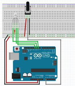
The following steps correspond to the picture above.
First, power the breadboard by connecting a wire from "5V" (power or VCC) on your Arduino to the positive row on the breadboard and another wire from "GND" (ground or 0V) to the negative row.
Then pin the potentiometer to the breadboard, connect pin A0 on Arduino to the central pin of the potentiometer and power the potentiometer with one pin on GND and the other one on 5V (on each power row of the breadboard).
Finally, pin the LED to the breadboard. Connect the longest leg to ground with a 220 Ohms resistor. The other legs must be connected to pin 9, 10, and 11 on the Arduino.
Attachments

Step 3: Code
Now let's write the code:
const int pot = A0;
//create a constant wich is the potentiometer and connect it to pin A0

const int green = 11; // same with the green pin of the LED on pin 11
const int blue = 10; // blue pin on pin 10
const int red = 9; // red pin on pin 9

void setup() {
  for (int pinNumber = 9; pinNumber<12; pinNumber++){
    pinMode(pinNumber, OUTPUT);
    }//these two lines mean that pins 9 to 11 are outputs

    pinMode(pot, INPUT); //this means that the potentiometer is an input
    Serial.begin(9600); // initialize the process to receive serial data
  }

  void loop() {
    int potVal = analogRead(pot);
    //potval is an integer that stores the value of the potentiometer

    Serial.println(potVal); // print it in the Serial monitor
    if(potVal<=340){
      digitalWrite(green, HIGH);
      digitalWrite(red, LOW);
      digitalWrite(blue, LOW);
      }/* all these lines mean that if potval is less than a third of the max
      value(1023), the green LED must be on. */

      else if (potVal<=680 && potVal>=341){
      digitalWrite(red, HIGH);
      digitalWrite(green, LOW);
      digitalWrite(blue, LOW);
      }/* same but if it is higher than a third and less than two thirds of max
      value, red LED must be on.*/

      else if (potVal<=1023 && potVal>=681){
      digitalWrite(blue, HIGH);
      digitalWrite(red, LOW);
      digitalWrite(green, LOW);
      }// same but between 2/3 and 3/3, blue LED must be on

    delay(100); //repeat the process every 100 milliseconds (0.1 second).
    }
What I did here is I divided the max value (1023) by 3. Here is how I got 341 and 680. But you could just use the 'map' value. I may update the code this way later.
Attachments
Step 4: Thanks !!!
Now, you just have to rotate the potentiometer and the color of the LED will change!
Please subscribe, share this project, and add it to your favorites !
Check out my other Instructables!
See you soon ;)
Hugo.T


