

Introduction: RGB Led Strip Bluetooth Controller V3 + Music Sync + Ambient Light Control


This project use arduino to control a RGB led strip with your phone via bluetooth. You can change color, make lights sync with music or make them auto adjust for the ambient lighting.
Step 1: Components


For this project you are going to need the following components:
- LED strips of course, i ordered 10 meter of high density RGB strips from aliexpress for around 1€/m:https://it.aliexpress.com/item/10000000224362.html... , the adhesive is pretty bad but other than that they are awesome for the price. when choosing what to buy you need to go for the RGB "dumb" strips, no adressable and no RGBW. Also take note of the power per meter rating of your strip and multiply it for the meters you are going to need to get a rough power estimate. 5050 LED strips are around 7W/m for the low density 30 LED/m type and 14W/m for the high density 60 LED/m type.
- 12/24v switching power supply, depending on your strips voltage. You can use an ATX power supply but in any case be sure to choose a power supply with a suitable power rating. I raccomend buying a power supply that has at least 30% more power rated than you actually need for the LEDs, expecially if you buy a cheap one like this: https://it.aliexpress.com/item/32304688758.html?sp... .My Strips were 14W/m, i needed to power 7.5m so I needed roughly 105W, I bought a 180W nominal power supply just to be on the safe side. I don't raccomend buying this if you are new to electronics as it has exposed high voltage terminals, do it at you own risk.
- Arduino, i used a PRO micro but you can use whatever you want, keep in mind you may have to change some pins and the name of the Serial port in my code if you are going to use a different micro controller.
- 3x N channel mosfets , I've gone with IRF3205 because I already had them on hand, they are capable of 80Amps and have a reasonable low on resistance so they should be plenty good. If you notice that they tend to overheat you can also add some heatsinks like i did.
- 3x TC4420 mosfet drivers, They might not be necessary depending on your power need, go on reading for explanation.
- HC-05 bluetooth module, be aware to choose a 5v logic level one or you might need additional circuitry (a voltage divider should work) to step down the voltage coming out of the TX of the arduino .
- 7805 voltage regulator/ 5v buck converter to power arduino and bluetooth module.
- 5x 0.1uF, 1x 100uF capacitors, 4x 10kohm resistors.
(optional)
- electrect microphone module , it consist of a microphone and an amp with adjustable gain that sends out an analog voltage ready to be read from the arduino. You can build your own circuit or don't use it at all if you don't want your lights to turn on to the rythm of music.
- photoresistor, you can also use a simple LED used as a light sensor but you must change the code for it to work.
Step 2: Schematic


Make the circuit on a breadboard to test it, replicate the mosfet driver circuit (second picture) 3 times, one for each channel, connect the 3 PWM output of the arduino to the PWM inputs of the driver circuit. If you don't want to use a dedicated mosfet driver IC you can build a simple push-pull driver using two NPN transistor, you can find more info on the internet. If you are planning to use the circuit for just a few LEDs you can directly connect the gate of the mosfets to the PWM outputs of the arduino via a 100ohm resistor, and add a 10Kohm resistor between source and drain of the mosfets, however this is not raccomended because it does not fully turn on the mosfets and so cause a lot of inefficency.
The 3 R G B pads of the led strip have to be connected to the drain of the 3 mosfets, and the other pad to +12v.
Step 3: Code
This is the code you need to upload to the arduino, what it does is basically using some low level registry magic to generate three 15KHz pulse-width-modulated signal (PWM) to drive the three mosfets with a variable duty cycle. In the loop it checks for incoming transmission from the bt module and when it does receive something it updates the color and the mode, also it saves all of that to the internal EEPROM so it remembers the settings when it is restarted. There are currently 3 modes implemented:
- Color mode: just display a fixed color.
- Music mode: turn off all the outputs for a brief moment if a sound treshold is reached, basically making a strobe light effect in sync with your music. If it does not work as intended you need to adjust the microphone sensitivity with the pot on the module, the treshold value in the code labeled as "thd" or the distance between microphone and sound source.
- Ambient mode: It measure the amount of light in the room via the photoresistor and fade the brightess of your chosen color accordingly. In the mobile app or in the code you can adjust the HIGH and LOW tresholds that determine on what value (0-1023) the lights go fully on or fully off. If you notice some flicker while in this mode you may want to move the light sensor away from the LED strips themselves in order to avoid interference.
Feel free to modify the code and add more modes, if you need my help understanding the code my email on top of the file.
Attachments

Step 4: Android App

You have to download this app: https://play.google.com/store/apps/details?id=com....
and also download and import the .kwl file.
If you want to create your own app that work with my code you need to have the following things:
slider for RED value that sends:" r+value between 0 and 1023+x" (es: "r130x")
slider for GREEN value that sends:"g+value between 0 and 1023+x"
slider for BLUE value that sends:"b+value between 0 and 1023+x"
slider for High treshold that sends:"h+value between 0 and 1023+x"
slider for Low treshold that sends:"l+value between 0 and 1023+x"
pushbutton that sends "m" for music mode
pushbutton that sends "a" for ambient mode
pushbutton that sends "c" for color mode
Attachments
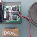
Step 5: Perf Board Circuit

When you have the full working circuit on a breadboard you can move it to a piece of perf board, use thick traces for the drain and source connection of the mosfets and screw terminals to connect led strips and power to the circuit. If you have thermal problems add some heatsinks, if you want to use a single heatsink for all of three mosfets be sure to isolate them from each other using thermal pads or you will short the outputs as the drain of the mosfets is internally connected to the metal part of the body.
Step 6: You Finished

Connect some led strips and power supply to your circuit and you are done.
That's it, at this point you should have a working THING.
Please let me know if you have issues or suggestions in the comment section.
P.S. In the video above the effectivness of sync with music is not shown as well as it is in real life due to low video framerate.


