

Introduction: Professional RIAA Equalization With Analog Electronics


What this report is about
Because I am a real audiophile and an electronics enthusiast, I often try to combine both. Most of my projects are about some analog electronic stuff, where I try to get the best out of audio records. The goal is on the one hand the circuitry, but on the other hand the basic understanding of audio electronics and its use for an optimal sound with more or less simple circuits.
Audio systems are predestinated for simple electronic circuits, because they only need a linear frequency behaviour up to 15Hz-25kHz and it is possible to build up really good devices with cheap and small OpAmps and a hand full of resistors and capacitors.
In this project, I will tell you some basics about vinyl recordings and the necessary equalization of the record. All in all this ends up in an amplifier circuitry with 4 OpAmps and some additional elements as a simple preamplifier and magnitude correction over frequency to get the normal sound back. I don't make projects like this because i want a perfect solution. I want to learn something and find possible solutions for the bunch of problems that will occur while I work on it. This project is still open and there's always room for some improvements, so just leave comments with questions, remarks, etc. .
Something general about vinyl records
Since it was possible to record data (e.g. music) on media like vinyl, the engineers had to force on one main problem with the technical process of grooving this data in a vinyl disk:
to get the same magnitudes of output signal, the grooved lines of the low frequencies had to be very big, while the high frequencies had to be very small. This is the case, because the (up and down) movement of the small turntable needle, which translates this movement to a voltage, needs this large movement at low frequencies for a similar magnitude in medium range frequencies. Grooving like that would hit the limits of the cutter while producing a record on a vinyl.
To get rid of this problem, the low frequencies were cutted a little bit smaller, while the higher frequencies were cutted with a little bit higher magnitude (general: emphasis).
Imagine now a linear working reading technique, which translates the signals as they are from the record:
--> the low frequencies are attenuated
-->the high frequencies are amplified
-->the frequency curve is distorted!
In the beginning of recordings, the recording companys had their own standards of a emphase the frequencies for a good recording. As you can imagine, this results in a more or less chaotic amount of distorted frequency curves and though it was hard to de-emphase the records for a proper playback at home.
The so called RIAA (Recording Industry Association of America) etablished a standard with a standardized equalization to improve the general sound quality of vinyl records. This RIAA curve is still the relevant kind of equalization curve, we have to consider, when we think about playing vinyl records.
Step 1: Technical Understanding and Simulating of the RIAA Curve


This curve shown above is described by 3 poles in the standard by giving time (frequency) of those:
T1=3180 µs (50 Hz), T2=318 µs (500 Hz) and T3=75 µs (2,120 Hz)
Those poles can be described as a highpass with T1, a lowpass with T2 and again a highpass with T3.
In 1972, the International Electrotechnical Commission (IEC) proposed a new, superior version of the RIAA curve. They added another pole, means another highpass, at 7950 µs (20 Hz). The idea was to reduce the subsonic output of the amplifier caused by rumble of the turntable [3].
You can try to simulate this frequency behaviour with LTSpice. We will simulate a lot of the following stuff with LTSpice, so this is a good preparation for the following steps of designing the amplifier.
Thus we know, which of these coefficients belongs to which filter, we can use the transfer functions of low and highpasses to get a proper result. LTSpice gives the great possibility to handle with Laplace transforms, so we can use the well known transforms of this filters (transfer function in Laplace notation).
lowpass = 1/(1+sT), highpass = (1+sT)
with s=Laplace transform variable, T=filter constant
Now just choose a voltage depend voltage source as shown in the picture and add the following command as "Value":
- Laplace=(((s*T0+1)*(s*T2+1))/((s*T1+1)*(s*T3+1)))/10
and the time constants as a parameter on the schematic:
- .param T0=3180us
- .param T1=318us
- .param T2=75us
- .param T3=3.18us
The factor 1/10 at the end of the Laplace transform indicates the attenuation, because the curve, we try to simulate here, has a zero at 1kHz and not at 0Hz. We simply shift it by -20dB. You can leave that part out, but it will get helpfull later on, when we try to flat this curve with our amplifier circuit.
If you are more interested in this topic of simulating the RIAA in spice, i refer to [1] and [2]. You can also simply google that topic or visit the LTSpice Yahoo group.
[1] http://www.hagtech.com/pdf/riaa.pdf
Step 2: The Inverse RIAA Curve

Think about this transferfunction as a transfer function of one whole system, described by the given Laplace transform A - the inverse would then be A_inv=1/A. Pay attention on the correction factor of 1/10, this should be a shift up to 20dB at 0Hz, so the correcting factor here is 10.
The transform looks like "Laplace=(((s*T1+1)*(s*T3+1))/((s*T0+1)*(s*T2+1)))*10" and the frequency response will show something like the picture above.
This is now the basis of our circuitry - the amplifier and equalization circuit must have a frequency responce like that for a normal and clear audio output from the vinyl record.
Some points are given with a value for necessary amplification [4]:
- 50Hz with 17dB
- 500Hz with 3dB
- 2120Hz with -3dB
- 1000Hz with 0dB
This fits to our curve in the picture above (checked in LTspice). Before we go deeper in the amplification circuitry and the de-emphasis to correct the pre-emphasis of our vinyl, we have to have a look at our electrical source: the transducer from our mechanical energy to the electrical energy
Step 3: Magnetic Cartridges

As you already know, the turntable has an transducer, to convert the engraved data via mechanical movement of a needle to a electrical signal. Although there are others than the magnetic ones, like piezoelectric or light based, I'll only cover the MC (Moving Coil), MM (Moving Magnet) and the MI (Moving Iron) cartridges, because they are most in common. The main difference is, as the names already predict, that in MM the magnet is the moving part, which is directly connected to the movement of the styles, while in MI the iron inside the coils is the moving parts. In case of the MC system, the coil is moved by the stylus.
Typical output values for both kinds of cartridges are up to ~10mV for MM and MI type and ~1mV for MC.
Obviously the MM and MI systems are preferable because of their higher output voltage, but MC have one big advantage: their voltage shows a really linear behaviour over frequency.
The MM system for instance has build in coils - e.g. 4, 2 for each channel. The channel separation for stereo sound is realised by grooving the different information on the left/right side of the running track of the stylus. So an impulse on the right side leads to more movement in the right coils and the other way around. The separation of the two channels is given for each cartridge system in dB @ 1kHz - mostly 20dB.
The picture above shows the frequency responce of a typical moving magnet system. In the hearable range, the system shows some minor deviations from the 0dB line up to 2.5 dB. This leads to distortions in our audio signal, but without a curve like that for our system, we cannot fix that. This isnt really as bad as you might think, because even if our system shows this behaviour, 2.5 dB are'nt really much. This behaviour also variies with the production date, so its not controllable, unless you cover the behaviour of your personal cartridge. Another point is, that the manufacturer often dont offer those detailed reports for their cartridges with some approximated measurements of the linearity over frequency like the one shown above.
So let us just choose one system, take it as a perfect manufactured and linear one over the whole hearable frequency range and only take care about the emphasis of our audiosignal from the vinyl record.
I chose a MM system for about 25 Euros: Audio Technica CN5625AL
Channel Separation 20dB @ 1kHz
Stylus force: 1.5-2.0 grams
Stylus form: conical
Output voltage: 4mV @ 1kHz
Step 4: Basic Functions and Blockdiagram

Since we know now a lot of facts about the idea behind pre-emphasis and de-emphasis and the source of our audio signal, we can now think about the basic functions of the amplifier system:
We need the component values for filters (low- and highpass, mixed) with the already given poles.
It is always cleverer to make sure that the frequencies above the hearable range cannot get into our system. We dont wan't to have some annoying noise through side effects like modulation in the active parts and so on and so forth (to cite one of my favorite application notes from AD "Noise reduction is not a mystical job for wizards..."[AD]. So just put an HF filter (lowpass with a cutoff frequency somewhere above 25kHz) in front of the system.
Now its time for some decisions:
Although it is often smarter to use batteries in self-made audio electronics, because it is the simplest way to avoid mains hum and ground loops, we dont want a battery as a voltage source in the completed circuit. We want a device next to our turn table, running without annoying battery changes. So, our device should be somehow mains driven with a AC DC converter.
REMARK: when i first builded up some prototypes, i used a 9V block as energy source, simply because it was very handy and easy to realize. Mains in combination with a ACDC converter is often a bad choice for the first test of an audio circuit, because it can introduce so many noises and you might think that it is your circuit which doesnt work. Remember that a cheap AC DC converter usually consists of a bridge rectifier and one or two capacitors to "flat" the 100Hz noises (shown in chapter 12). That may work for driving a LED circuit, but it will make problems in audio electronics. So just to make sure, that i didnt introduced more noise than necessary, i used batteries at first. After everything worked, i switched to ACDC converters (chapter 12).
Lets have a look at our sink: the AV receiver. I have a sony av receiver str-de495 with an input impedance 50kOhm. We don't want to have a too quite or too loud sound, so I assumed 1-2Vpp to be a proper range for an input signal voltage range. We handle with voltage bridging in this case, so we have to make sure, that our output resistance is much lower as the 50kOhm of my receiver - since the voltage will come directly from a low impedant output of an opamp this shouldnt be a problem.
With the given 4mV of our cartridge and the 1-2Vpp (500mV-1000mV amplitude) output voltage of our amp we need a over all gain of 125-250. To make that adjustable we have to place something like a potentiometer to vary the voltage range.
Dont forget: we have to build two channels, since the signal from our vinyl record is in stereo!
Step 5: The De-emphasis
As i already mentioned, i need a couple of filters to flat our distorted frequency response to the wanted shape.
In analog electronics there is alway the possibility to use simple passive filters from the combination of resistors and capacitors. But there are some reasons for not only choosing passive filters in this case. Active filters do have some properties, which can be helpfull here.
Just to keep it short for newbies in electonic filtering: to get really sharp edges at the cut off frequency it is normal to make a use of the oscillation of a system. Of course, you dont want a system to oscillate, but you can use the resonance peak to get a sharp edge in the frequency responce at the cut off frequency. That becomes really important when you higher the order of your filter. Passive filter become tricky here, because cascading filters means that the cut off frequency starts to get a little bit unsharp in the bode diagram. You could use now inductors to build up an oscillating circuit with the resonance frequency = cut off frequency to let them compensate the unsharpness and to get a sharp edge here, but inductors in the important frequency range would be heavy and expensive. Thats one of the main reasons of active filters: use opamps as oscillators for a staying sharp cut off edge in the bode diagram, even when you cascade filters up to a higher order.
The main reason for using an active filter here is: decoupling the passive filters from each other and amplifying to some value (think about suppressing the 4mV - whatever comes out is suppressed by the filters and again very small). On the other hand, active filters can easily combine multiple passive filters - e.g. it is possible to combine the 50Hz LP and te 500Hz HP in one active filter - this is exactly what i'll do here.
All other filters will be passive ones, positioned partly in front of or behind the active one.
Step 6: Filter Design Pt. I


The active Filter consist, as shown in the picture above, of 3 resistors and one capacitor - it is working as a non inverting amplifier, defined by the all over gain with G=1+ (R1+R2)/(R4), which will be something around 110 in this case. This amplification will partly be decreased by a few dB due to the attenuation of the following filters. R4 also guarantees that the input currents of our amplifier U1 can flow to ground.
The filters are defined by the positon of the capacitor C1 and its size (you can of course use other values of the resistors and capacitors, but pay attention on the cut off frequency):
- R1||C1 build up a lowpass with the cut off frequency of 1/(2*pi*R1*C1) = 50Hz
- R2+C1 build up a highpass with the cut off frequency of 1/(2*pi*R2*C1) = 500Hz
Both filters compensate each other so the curve shown in the second picture!
If the attenuation is too high or low later on, we can simply fix that by changing R4 to a higher or lower value.
Step 7: Filter Design Pt. II


The two filters in front of the OpAmp in the schematics above together with the curve show the behaviour of two passive filters (HP @ 10Hz + HF LP @ 85kHz) working in combination as a bandpass filter - which filter our important range out of all input signals.
Input = low freq. rumbling + usefull signal + HF noise
Output = usefull signal
Step 8: Filter Design Pt. III


Now there is one filter left, which i placed after the active one in form of a passive LP at 2120Hz. Altogether will become the wanted RIAA de-emphasis curve, shown in the picture above.
Step 9: Test of Our De-emphasis in LTSpice


We can now try to give our laplace trafo as an input in our filter in LTSpice. If everything works, we will hopefully get a flat curve in the range of 20Hz-20kHz.
I just added the curve of our Laplace function to the input and made an AC analysis like it's shown in the schematics above.
As you can see in the resulting curve, the region of importance is really flat now. The frequency around 20Hz is a little bit attenuated and the frequencies in the range of 3kHz - 20kHz are a little bit amplified, but both arent in a considerable range (in that range of dB not hearable). The frequencies in between are very equal to each other and additionally amplified with something around 20dB.
Since our theoretical circuitry of the de-emphasis works, we can think about the amplifying part and the whole realisation.
Step 10: The Right Opamp


When we choose an amplifier for a special application, we have to know, which properties of the possible opamp are important. In our case a clear output signal is very important. Since we use an amplification in our filter circuitry of around 100 (the 125 of the op amp are damped by the filters to around 20dB = 100), we dont need a very high amplification in the secons step. The amplifier must have a low distortion, low quiescent currents and so on to make sure, that the signal doesnt get distorted. In the frequency range we use, nearly every opamp is usable. Another important point is the supply range. We have to choose either a symmetric or a nonsymmetric power supply.
Of course there is not the one and only amplifier for this kind of circuitry, but there are special audio opamps which have some advantages in this field of application.
The LM386 is very famous for its behaviour as an audio opamp. It has adjustable gains in steps from 20, 50 to 200, has the possibility of an internal bass boost and has a ground reference input (nonsymmetric supply).
This IC gives the great opportunity to change the behaviour of our second amplifier step with just a few resistors/capacitors. Add a resistor and a capacitor = bass boost, leave some out = gain of 20, and so on and so forth.
I have positive experience with this opamp for audio amplification, because its really simple and cheap as well.
I choose the datasheet circuitry with gain = 20 for my second amplification stage. I additionally will use the bass boost side path from pin one to pin 5 with a switch, so i can decide, if more bass is necessary by simply turn it on or off.
Datasheet: http://www.ti.com/lit/ds/symlink/lm386.pdf
Example (in german): headphone amplifier with LM386: http://www.troeszter.net/Download/Audio/LM386-KHV....
Step 11: The Active Filter - Opamp

The filter opamp dont need special behaviour for its function as a simple amplifier with a gain around 100 and filtering the signal except for a low distortion. Nevertheless we can make our life easier when we use a dual opamp, so we can filter both channels in one opamp.
I chose the LM358, because i already had it available at home - you can choose another one, but you have to pay attention on a proper supply (like it is done for the LM358 in the following steps)
Advantages are e.g. the supply range (you can choose between single or dual supply) and its cheapness. Since we know now all our active components, we can choose now a proper supply for our device.
Datasheet: http://www.ti.com/lit/ds/symlink/lm158-n.pdf
Step 12: Choosing a Proper Supply


As i have already mentioned, i always test prototypes of audio circuits with batteries like the 9V block, even if i want a mains driven device. This is just a way to get rid of the mains hum problems in the test phase of a project, which occur due to the electrical connection to the mains.
For now the 9V are given, but may be changed later on when i upgrade the device with an AC DC converter as a power supply.
We have to have a look in the datasheet of our active componentes: both will work with 9V single supply!
BUT: only the LM386 will work with a ground referenced input (no DC is necessary to avoid clipping of the signal)
The LM358 works with a single supply, but the signal must be positive in all time points = above the 0V line. The output of the cartridge is, if the ground pins are refered to ground, both negative and positive. We have to add a DC voltage, to raise our signal in a proper range: normally 1/2 * supply voltage is choosen.
This can be realized with a supply splitter / virtual ground circuitry.
I always use one of the following two ways to get the supply voltage splitted:
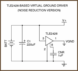
1. The easiest way is to simply use an IC, which splits the supply voltage up to the relevant voltages 0V, supply voltage, and 1/2 supply voltage. One possible IC, which i really like to use, because it is so simple, is the TLE2426 supply splitter from TI. This can be build up in a circuit for noise reduction shown above and will give a reliable splitted supply voltage. This IC works over a large range of possible supplies and is really easy to implement.
Datasheet: http://www.ti.com.cn/cn/lit/ds/symlink/tle2426.pdf
[6] picture http://tangentsoft.net/elec/bitmaps/vgrounds/tle24...
2. One disadvantage is the high price for this IC. You can also consider about building the ICs functionality with several resistors, capacitors and an opamp. The supply splitting is not a big deal, so this may also be a good way to get the result. A supply splitter works basically like a simple voltage divider made of two equally sized resistors between the supply and ground. The supply is splitted up to 1/2 in the middle of the resistors. This voltage is now driven trough a voltage follower opamp to decouple the voltage from the resistors - the voltages are driven by the low impedant output from the opamp. Additionally there are always some capacitors in this kind of circuit to short-circuit all non-DC parts to ground.
The IC L165 is a large power opamp, driving currents up to 3A and comes with a datasheet version of a supply splitter. Except for the disadvantage, that the opamp can become really hot (i burned my nose once! dont ask how =D) and that the opamp needs min. 8V supply, this circuitry is really good as well.
Datasheet: https://www.tu-chemnitz.de/etit/zentral/ddr/ds/L16...
I used the TLE2426 at first, but broke my last IC. Thats why i had to switch to the second circuit with L165 afterwards.
Long story short: both are working well with my preamp circuit!
Step 13: Coupling and Decoupling

When we use such a supply splitter for one opamp (LM358) in combination with an opamp, which doesnt need such a virtual ground (LM386), we have to couple and decouple our signal carefully on and off the DC voltage (1/2 supply) in the right parts of our circuitry. Only in this part the ground is refered to our virtual ground while the whole LM386 part is connected to the real ground. The decoupling is realized by highpasses with a very low cut off frequency (or coupling capacitors, which will work as lowpasses together with the load resistor). Just choose a very high capacitor value for coupling and make sure, that the cutt off frequency doesnt influence our important signal range.
Coupling capacitors are:
- C3 (part of the highpass at the input)
- C7 (together with R7 a LP with a very low cut off frequency
All ground references in between have to be connected to the virtual ground with 1/2*supply voltage. Now the LM358 is driven with a symmetric supply, while the LM386 is still working with its single supply.
The capacitor C8 is again kind of a decoupling capacitor (working as a LP with the input resistance of my AV receiver) to avoid offsets on the receivers input due to the amplification.
The C1 at the supply voltage input of the filter opamp simply short circuits again noise and non-DC parts to ground to avoid baseline drifts or other annoying side effects (unlikely with battery supply)
Step 14: The One-channel (mono) Prototype


I determined every part of the circuit till now:
The filter circuit works in theory. I will use the supply splitter from the L165 datasheet. The amplifier circuit of the second stage is from a datasheet (LM386) as well. R11 and C9 build the "bass boost" path, but i wont connect them directly, because i want the possibility to switch this effect on and off. Somewhere in that path will be a break in the circuit.
R8 and R9 represent a linear potentiometer. With R9=0 the signal is short-circuited and the volume is zero. With R8=0 the volume is maximal and the signal gets fully amplified by the LM386 circuit with the factor 20.
The variation of R8=5k-R9 with steps from R8=0, 1k, 2k, 3k, 4k, 5k is shown in the bode diagram above.
The list of elements is in the end of this project as a pdf file.
Step 15: Testing the Mono Prototype


I tested this prototype in three steps.
At first, i measured the DC voltages on important points of the circuit. Where is the virtual ground, where is the real ground, is everything where it should be? If you are unsure, just unplug the opamps before you connect the supply or implement a diode as polarity protection between ground and supply voltage (thats what i did and trust me - its worth it!).
After everything is checked, i used a function generator and an oscilloscope as shown in the pictures to test the circuit. Pay at first attention on the DC offsets again, is there everything right? Then introduce a sine wave e.g. with 1kHz (common test frequency for audio circuits). Hows the shape at different frequencies? Deforming of shapes can be one big reason for shitty sound!
Another main question is the question about the right attenuation: I fixed the gain and measured output voltage amplitudes with different frequencies of a sine wave with e.g. 20mV peak to peak. The amplitudes should show the behaviour over frequency like it is shown in the curve above (that means the form should be the same, absolute values may vary because of the different gain).
Last but not least: check the system with a vinyl player and the receiver. If something sounds wrong go back to the oscilloscope and check the circuit.
One of my main errors:
Incorrect filter placement at the input terminal: capacitors at opamp inputs instead of resistors lead to ground. The input currents from the opamp load up the capacitors and lead to a DC-line shift and clipping of the signal with some time. Another important point is the virtual ground terminal. The whole circuit will show some strange behaviour if this circuit part fails.
If everything is right:
build up the second channel and switch from battery supply to mains.
Step 16: Mains and Audio Circuits


The idea is simple: disconnect the battery and grab an old mains adapter with e.g. 16V. Check, if the voltage is in the range of the parts you use and then connect it.
But as i already mentioned: cheap mains adapters may be a proper supply for some motors or LEDs, but not for audio circuits. The picture above shows a combination of two inductors in transformer configuration (230V_rms AC --> ~16V) and a bridge rectifier to get the absolute value = 100Hz rectified sinusoid. When the resistance R1 is a fixed load resistance, only the size of the capacitor flats the curve to a almost DC voltage. But that "almost" is the problem. Even if the capacitance is really high (e.g. 100uF or higher) the supply voltage contains this 100Hz humming (and harmonics).
To prevent the circuit from this humming, you can use big capacitances at endangered parts (e.g. C1 in the circuit) or directly at the supply input on the board. I use a capacitance of 1500uF between supply voltage and ground directly in the input. Another technique, that i was recommended to realize: if a single capacitor wont work, try a capacitor in series with a inductance between ground and supply.
In my case both doesnt works really well. The simple solution is to use a voltage regulator like the well known LM317. This IC comes with very high ripple rejection and is really easy to handle. I used the circuit from the datasheet shown above and simply changed the values from R1 and R2 to the necessary values for converting my 16V mains adapter output to fixed 10V (you can choose other ranges). You can use formulas for the calculations, several calculators in the internet, or use an android app like i did. The resistor values are R1=200 and R2=1400. The power dissipation will be around 300mW, but that is according to the datasheep absolutely in the range at an ambient temperator of ~25°C.
Because i recognized some heat at the LM317 and the opamp L165 I connected two old heatsinks to the pins of the ICs. One mistake i made here was building the ICs next to each other, with the idea to connect both to the same heatsink. But that will short-circuit the circuit! So make sure that there is no electrical connection between both heatsinks. Nevertheless both heatsinks next to each other look quite good for me, so I kept it that way.
This supply circuitry works perfectly with my mains adapter.
Datasheet: http://www.ti.com/general/docs/lit/getliterature.t...
Step 17: The Two-channel (stereo) Prototype


After building up the mono channel version, it is time to build up the two channel version.
I used the mono version and just added another circuit for another channel, to make it as simple as possible. Although that makes the whole circuit non symmetric, which can have negative effects on the resistance against mains hum noise on the signal, this hopefully wont have effects on my circuit. Mains hum shall not appear if my PCB layout is done correct.
Step 18: Routing and the PCB


Due to shieldung properties i used one complete layer as ground. The routing is done with eagle and the whole pcb is less than 10*10cm^2. I ordered 5 of this pcb from a distributor in china and the quality is really great!
The (more or less) necessary elements for the terminal are:
- 2 potentiometers for the channel adjustment
- one switch for on / off
- one dual switch for the bass boost on / off
- LEDs for bass boost/ power on indication
- plug for power supply
- plug for audio output (jack connector)
- two plugs for the chinch audio input
The list of components is attached.
This project is part of a whole development process of a selfmade turntable. The Instructable for the turntable will follow in the next months.
Attachments


Participated in the
Makerlympics Contest

Participated in the
123D Circuits Contest


