

Introduction: Radius Measuring for Reverse Engineering.


I needed to duplicate some curves from a 1960s racing motorcycle crank- and gear- case to a new set being milled from the solid. I needed to measure the radii of several curves so that I could write some G-code to direct a CNC mill to trace out the same shapes.
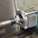
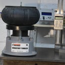
The first illustration above show what I made and the other photos show some commercial offerings to do this job. These special commercial gauges and calipers tend to have starting prices of several hundred dollars.
With three points on a circle you can determine the radius of a curved workpiece with a little bit of geometry (see a later step). In fact this three point method is how the above commercial gauge and calipers function. The commercial gauge above is not a standard digital gauge, the display is multi-line and the gauge will have special firmware to calculate and show the radius directly. The vernier calipers achieve the same by using an appropriate scale. The jaw angles of the digital calipers are chosen so that the opening displacement is equal to the radius. This allows the use of a standard mass produced digital display to display radius directly.
During a quiet moment I decided to make my own digital gauge based device and the main thrust of this Instructable is to describe just that. The cost of my design is just that of a digital or dial gauge, the downside is that the reading needs some manipulation to get converted into a radius measure. Do not worry or stop reading, I present a graph for reading the radius knowing the gauge displacement. I also include a link to some software that I wrote to calculate the radius for any size measuring device.
Supplies
- 1 Dial gauge or digital gauge.
- 1 Plastic clamping screw.
- 5 mm (3/16") ball bearings, 2 for each size device.
- Solder.
- Soldering flux.
- Short length of 5 mm (3/16") steel rod.
- Scraps of aluminium.
Tools
- I used a milling machine but that is not necessary, a hack saw or band saw would do the job.
- Some drill bits and a 6 mm or 1/4 thread tap.
- Mill, drill press or pistol drill, listed in order of preference.
- Gas torch, large soldering iron or high temperature hot air gun for soldering.
Step 1: Nature of the Task.


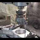
The two photos show an number of curved surfaces for which I need to measure the radius.
Step 2: Radius Templates - a Simple Way to Measure

There are many ways to reverse engineer the curves, as always those available for any particular job are dependent on the size of the budget. At the high end it would be a CMM and at the low end it will be Radius Templates (often called Radius Gauges). I have 6 sets of radius templates giving me a range of 0.3 mm to 100 mm, both internal and external radii. (pictured above). I am doubtful as to the usefulness of the very small ones and I mostly use the 25 to 50 and 52 to 100 mm ones. To use, it is simply a matter of matching the curve to a template, this is made easier by shining a light from the back side. If the templates are well made then this can be quite accurate, however it can be time consuming if you need to try several templates before finding the matching one.
The two end radii on the top cover in the right hand image of the cases (shown in the previous step) were 105.8 and 228 mm, too large for my templates. I can use the DROs on my mill to determine the coordinates of three points on each curve. With three points on a circle you can determine the radius with a little bit of geometry. This is quite time consuming though.
Step 3: Making the Beast

The range of radii that such an instrument can measure depends on the width of the two outside contact points on what I’ll call “probes”. It is common to have several probe blocks in a set to cover a wide range of radii. I initially made one that had the probes ground to a point with the point spacing of 50 mm. I thought that this should do reasonably well for the size of curves that were likely to be of interest. That proved to be the case. The 50 mm radius gauge as first made is shown on the left and a prettied up version on the right. The tarting up was not purely for visual effect, one of the first real applications for it was hampered by the bulk of the original. The original size and shape was just a consequence of the piece in the scrap box.
The making could not be more simple. I drilled a hole in the centre to suit the stem then cross drilled and tapped for the clamping screw. Then I drilled two holes for the rods with their sharpened ends. I made these a slight interference fit but a looser fit and Loctite would do OK. that is all there is to it.
I do not like using steel screws to clamp a gauge support tube and the black clamping screw is plastic.
It took me only 26 minutes (yes, I did time it) from the start of looking in the scrap box to taking my first measurement.
Step 4: Breeding

I had three identical pieces of aluminium in the scrap box and so after testing the first I decided to use the other two pieces to make two more probe blocks with 30 and 75 mm spacing. I also decided to make these with ball ends rather than points. I used a milling machine to make the blocks but they are very easy to make and could be done with nothing more than a hacksaw and drill.
Step 5: Ball Ended Probes

I made the ball ended probes by soft soldering ball bearings to steel shafts. I used soft solder because there is much less chance of overheating and softening the balls than if I used silver solder or braze.
A finished probe on the left in the above photo, on the right the steel shaft is supported by a strong magnet. The idea behind that was that it would hold the ball in place whilst being soldered. The end of the shaft was given an indent with a drill for the ball to sit in. Flux was applied to the indent, the ball added and then it was all heated and soldered.
This is best seen in this short Video link
Step 6: Keeping Them Safe

Of course the set would not be complete without a wooden box.
Step 7: Method of Use


Firstly the radius gauge is placed on a flat surface and the digital gauge zeroed. Of course the same can also be done with a dial gauge. When setting the zero and doing the measuring, the gauge should be held square to the work piece. I rest it against a square to ensure that it is upright. The first photo shows the zeroing and the others show typical usage.
Once zeroed it is held onto the radius to be measured and the reading noted. What we do with the reading is described in the next step.
Step 8: Getting the Radius

From the previous step we only have a reading for the displacement of the digital or dial gauge, but this is not the radius. As already mentioned, commercial units have special gauges with internal soft-/firm-ware written to display both the displacement and the radius directly, and are priced accordingly. The use of a standard type of digital gauge demands that the radius has to be calculated from the displacement and physical details of the block in use. To avoid the tedium and time wasting that would be involved with calculating this for each reading I have written some software that I have made freely available. For those interested in the calculations I have shown these in a following step.
The software can be downloaded from Radius gauge software
Just copy it to a folder of your choice and run the file. There is no install procedure, the programme makes no changes to your registry, it leaves no cookies and does not spy on you. Your computer does not have to be connected to the net.
BTW this is a 32 bit Windows programme which should run on macs and Linux with Windows emulators as well as Win32 and Win64 machines from Windows95 and up.
The illustration shows a screen shot of the software. There is a pop-up window which displays a table in which you can enter the physical details of up to ten measurement blocks. Each can be assigned a name for easy recognition, and the ball diameter and centre spacing can be saved. For example, as stated I have three blocks and I simply name them as “small, medium and large”. It is only necessary to select the block in use from the list and enter the displacement of the digital gauge for the curve radius to be calculated and displayed. These radius gauges and the software are capable of measuring both inside and outside radii.
This is not quite as convenient as the direct reading from the commercial units but it does not cost several hundred dollars either. If you need to do a lot of such measurements in a commercial environment then get the commercially made version. For hobby or occasional use then the DIY item makes sense, especially if you have a digital or dial gauge.
Step 9: Using the Software

The first thing to do is click on the Gauge button and then enter and Save your gauge specifications. That is simply the ball diameter and probe spacing as shown next. The units can be either metric or imperial but they must be consistent throughout.
Select the appropriate gauge and click Continue. Select whether internal or external curve, zero the gauge and take the reading. Enter the gauge reading in the gauge displacement box and click the Calculate button. That is all there is to it.
Step 10: A Few Words About Accuracy


With any measuring device or system it is important to understand the factors that affect the accuracy of the measured data. There are several sources of potential error in these devices, let us consider some.
The digital gauge itself. Firstly, there is the minimum resolution, this is typically 0.01 mm so we can not measure any closer than that but in practice the accuracy will be a few times worse than this. To see the effect of this on the radius calculation, consider the case of using the 75 mm block with a +/- error of 0.03 about a displacement of 5 mm. For a reading of 5.03 the radius would be 139.9 mm, and a reading of 4.97 the radius would be 141.6 mm. In other words an accuracy of +/- 0.03 about a nominal displacement of 5 mm gives us a radius range of 1.7 mm. This is just one example only applicable to this block with a displacement around 5 mm. The potential error range will vary with the block and the radius being measured.
The relationship between the measured radius and the probe spacing. Check the illustration above. If a gauge with close probe spacing is used on a large radius then the gauge displacement will be small and so the error in the gauge itself will be a relatively high percentage of that measured, thus giving an error in the radius. On the other hand if the probe spacing is near to the diameter of the curve then the radial position of the gauge as a whole will be ill defined and the error in the measured displacement will be correspondingly high. There is a reasonably wide overlap between a given block size and another but it is necessary to choose a probe spacing between these two extremes.
Calculation error in the software. These calculations are done with a large number of significant digits and the errors from this source will be minimal compared to the other error sources and can be neglected.
Dimensional errors in the specification of the probe spacing and ball diameter. It is not important that the probe spacing is made accurately to a specified dimension, but is is desirable that the actual dimension is measured accurately. For example, what I call the 30 mm block measures up as 29.195 mm and that is the value used in the software. This spacing and the ball diameter can be measured easily and accurately with normal micrometers. The gauge stylus should be central between the probes but there can be a moderate tolerance on that because a lateral error here will only produce a small displacement error. Let us consider the 75 mm block again with a 5 mm displacement and the same +/- error of 0.03 mm in the probe spacing. For the case of the spacing at 75.03 mm the radius is 140.85 mm, and with a spacing of 74.97 mm the radius is 140.63 mm.
Consider the graph above. We can see that the slope of the curve on the left side is very high. That means a small variation in measured displacement gives a large variation in calculated radius. In other words the error in the radius is sensitive to any gauge error.
Conversely at the large displacement end of the curve the slope is very low. That is the calculated radius is quite insensitive to errors in the measured displacement. However, as pointed out above when the probe spacing approaches the curve diameter there is an increasing lack of precision in the probe block positioning counteracting the effect of the decreased sensitivity to errors in the displacement.
Step 11: The Geometry Behind the Calculations


We need to calculate the curve radius from the 3 contact points of the instrument. If you search the net for calculating a radius and/or centre position of a circle given 3 points you will likely find descriptions of the development and solution of three simultaneous equations. This is quite valid but I normally use what seems to me to be an easier method. Consider the first diagram with 3 known points A, B & C on the circumference.
Firstly we calculate the slope of the two lines AB and BC, then we bisect lines AB and BC with normal lines (shown in red), these will meet at the centre, The slopes of these two lines are obtained by multiplying the reciprocals of the slopes of AB and BC by -1. so we can easily solve for the coordinates of the centre at O. It is then only a matter of calculating the distance from O to any of the points A, B or C to get the radius R, shown in green using point C.
This method applies to any positions of the 3 points. Fortunately we can simplify the calculation further in the case of the radius gauge because points A and C are symmetrical about point B. The second diagram shows this, for simplicity I have drawn this with OB along the X axis.
Due to the symmetry the angles OXA and OXC are 90 deg. The length AC is simply the probe spacing and AX is half of that.
XB is the displacement that we measure.
Thus the angle ABX (also ABO) is arctan(AX/XB), by symmetry we can say that BAO = ABO.
Knowing that all triangles have internal angles which sum to 180 deg. We can then calculate AOB = 180 -BAO -ABO or 180 -2*ABO.
The radius R=AX/sin(AOB).
It does not get much simpler than that.
The above calculation is valid only for point contact because it ignores the ball radius, implicitly assuming that to be zero. However, using this calculation with ball ended probes just gives us the radius through the ball centres, so we only need deduct the ball radius from the calculated radius to get the workpiece external radius. For internal radii we add the ball radius to the calculation. My software does this automatically.
Step 12: Conclusion

With a minimum amount of work and materials I have created a useful and reasonably accurate measuring tool which would have cost several hundred dollars from even the usual cheap internet sources.
My contact info


