

Introduction: Raspberry Pi Barometer Weather Clock

In this instructable I'll show you how to build a basic Thermometer / Barometer clock using a Raspberry Pi 2 with a BMP180 I2C sensor displaying on an Adafruit 4 digit 7 segment I2C display. The Pi also uses a DS3231 real time I2C clock module to keep time when the Pi is restarted.
The clock loops through 4 stages for 5 seconds each. First it shows the temperature in Celsius, then in Fahrenheit then the barometric pressure in kPa *(it walks this number to the left due to limited number of digits) and finally it shows a trend of barometric pressure change between now and the average of the previous hour.
What makes this clock different to most is that it uses a MySQL database on the Pi to log data from the BMP180 every minute. As the current barometric pressure is not as valuable as its movement up or down over a given period of time, it uses this database to calculate an average for an hour span between 2 hours and 1 hour ago and compares that to the current pressure. A significant increase in barometric pressure usually indicated an improvement in weather conditions vs a big drop could warn of an impending storm.
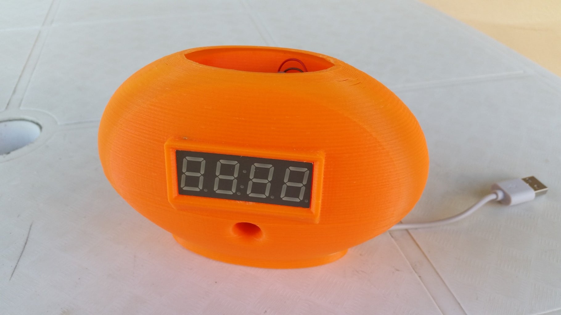
The clock is housed in a 3D printed ABS housing with the BMP180 in a vented cap on the back of the clock to prevent the heat generated by the Pi from affecting the temperature readings. I'll provide the Autodesk 123D Design schematic if you want to print your own.
The clock is powered with a standard USB wall wart and draws around 450 mA in total.
I wont go in to too much details on the basic setup of the Pi and I2C as this has been covered in many other instructables to which I will provide links.
Step 1: Prepare the Pi

Set up your Raspberry Pi - Details at Raspberrypi.org
- Download and install your selected Linux Distribution on an SD card - I used Raspbian
- Plug in the pi and boot it up
- I used a micro WiFi adapter to connect the pi to my router as the clock housing obscures the Ethernet port.
- I used headless mode where you connect to the pi using SSH so all you need plugged in is the power.
Configure I2C on the Pi - I followed these instructions on the Adafruit site.
Step 2: Wire It All Up

All the modules I use in this project are 5V tolerant and use I2C which is a 2 wire protocol used for IC's to communicate with each other, so the wiring is pretty simple. Connect all VCC to 5V, all Grounds together and all the SCA and SCL lines together as per the schematic. Job done.
Step 3: Test Your I2C

Part of the I2C installation is to run i2cdetect which should look like the attached image if everything is wired up correctly.
Below are the matching addresses
- 0x70 = 7 Segment Display
- 0x77 = BMP180 Thermometer / Barometer sensor
- 0x68 = DS3231 Real Time Clock module
- 0x57 = DS3231 on board EEPROM for storing alarm data.
Step 4: Install MySQL and PhpMyAdmin

Installing mySQL is fairly straight forward if you follow the tutorial here
sudo apt-get install mysql-server
I also installed phpMyAdmin which is a web site that runs on Apache which you can use to create and manage mySQL databases. Tutorial here
sudo apt-get install phpmyadmin
Once installed I set up a database called BP180 using phpMyAdmin with the structure as per the image.
I also make use of a python module called mysqlDB which you can install using
sudo apt-get install python-mysqldb
Step 5: Install Python Modules
Download and install the below python modules which you will use to connect to the sensors.
- Adafruit_BMP085 module
- SDL_DS3231 module
- Adafruit 7 Segment module
Step 6: Code to Log to Database
The below code snippet is used to log the temperature and barometric pressure and is called from a cron script (Linux scheduled tasks) that runs every 5 minutes. To learn how to use crond check out this tutorial.
NB! Don't bother trashing my coding skills, I'm not a developer so yes there's probably a million better, faster, smoother, cleaner ways to do this.
You'll notice in the code the temperature is decremented by 7 degrees which is equivalent to the heat generated by the Raspberry Pi even with the BMP180 mounted on the outside of the housing. When I originally had it inside the housing it was about 15 degrees hotter than ambient. It seems to be pretty linear, but I haven't had the opportunity to test any extremes. Feedback of your experiences would be appreciated.
Attachments

Step 7: Code to Display Temp


This code is called to cycle through the display as per the introduction.
Again, I'm not a developer so the code is really rough, but it works.
Attachments
Step 8: 3D Printed Enclosure


Next is the design of the enclosure. This was quite challenging as the shape is prone to warping because parts of the outer shell is only 2mm thick. I first drew mock ups of the Pi and all the parts and then designed the enclosure around it. The print took around 7 hours on my RapMan 3.2 (which is a pretty slow printer) at 0.25 layer depth.
The attached schematic is done in Autodesk 123D Design which I think is a fantastic piece of free software.
Note some of the holes like the ones needed to mount the Pi are not in the design as its better to drill these afterwards in case your print warps a bit. Steady hand a 3 mm drill bit is all you need. Mark the depth on the bit with some masking tape so you don't accidentally go straight through your 7 hr print like I did.
Attachments
Step 9: Things to Do

- The Real time Clock was an addition after the enclosure was printed for the 5th time so it is currently hot glued onto the side of the enclosure which does not look good so I would like to re-do the design and add a spot for it.
- The brightness of the 7 segment display is currently set to it's lightest which is not optimal for strong light conditions. I would like to add a photo resistor to the top of the enclosure and adjust the 7 segment brightness based on the ambient light conditions.
- There are some minor design issues with the base cracking which will also be fixed.
- Any ideas are welcome.
I hope you enjoyed this instructable and found it inspiring enough to get you going. The idea is to provide a platform that you can use to add your own ideas. Have fun!

Participated in the
Tech Contest


