

Introduction: Raspberry Pi Power & Cooling Mods


It's a little embarrassing to admit to having ten Raspberry Pis doing various jobs around the house but that said, I've just bought another one so I thought it would be a good idea to document and share my standard Pi modifications as an Instructable.
I add these mods to most of my Pis - they allow any model of Raspberry Pi to be powered from a spare power supply which otherwise would just be stuck in a drawer - being able to use an otherwise unwanted power supply should save you a few pennies and this arrangement can also provide a useful source of power for other devices such as relays. The cooling mod makes the use of the display and camera connectors more difficult but can stop the Pi throttling back when overclocked or undertaking processor intensive work. Access to the GPIO connector isn't normally impeded but you do have to position the fan carefully...
I've divided the Instructable into two parts to ease readability - Part 1 covers the power supply modification, Part 2 the addition of a cooling fan and heatsinks. The possible novelty of part 2 is the use of a 12v dc fan powered from the 5v dc output of the voltage regulator. The use of a 12v fan in this way is to provide a modicum of cooling with reduced noise, a feature that's needed when the RasPi is used (as an OSMC media centre) in our living room as my partner can hear a pin drop from well, virtually any distance you care to mention....
Please note that I've tried to pitch the detail to cover as wide a readership as I can but some basic electronics skills are necessary, such as soldering, using a multimeter etc. I apologise therefore if the following reads too simply or assumes too much - any and all constructive comments are of course very welcome!
Step 1: Part 1 Power Supply Mods: Tools & Parts


Parts:
- (A Raspberry Pi and case) - a transparent case makes these mods easier but an opaque case is not a show-stopper.
- A junk drawer AC to DC power supply, minimum output power 18W, 9v dc to 30v dc.*
- LM2596 DC-DC Switching Adjustable Step Down Voltage Regulator Buck Converter (available on eBay from multiple different sellers)
- DC Power Supply Jack Socket Female Panel Mount Connector 5.5 x 2.1mm or whatever you need to fit the power supply above. This is the most common though. (eBay, multiple sellers)
- A sacrificial micro USB type B lead (junk box) OR
- 1-off micro USB Type B 5-Pin Male Soldering Jack Socket Connector (eBay, multiple sellers)
- Two 150mm lengths of multi-strand equipment wire (eg) copper speaker wire.
- Two insulated stand-offs (short lengths of biro case make excellent stand-offs if you don't have any in your junk box)
- Two 2.8mm dia self-tapping screws (junk box) - these only have to be as long as is needed for the thread to go through the case - I used 12mm long screws.
- 2.5mm ID heatshrink & 1/4" ID heatshrink to suit (see step 5) (eBay, multiple sellers).
Tools:
- Soldering iron & multicore solder.
- Multimeter capable of measuring resistance and dc voltage.
- Heat gun (for heat shrink)
- Hot glue gun (not needed if using a sacrificial USB lead)
- Fine marker pen
- 1.5mm and 2.5mm HSS drill bits and drill.
- Wire cutter and stripper.
*Notes regarding the choice of power supply:
The important parameters are the output voltage and power. You need to provide the LM2596 regulator with approximately three volts more on its input than you need on the output, so for the 5v output needed by the Pi, you need around 8v on the input. I'd recommend a little more to be sure, hence the 9v minimum above. The maximum voltage you can use is around 35v for some models of this regulator, higher for others. I'd stick to 30v max.
The power supply also needs to be able to provide enough current to the Pi (see here for the current requirements for different models of Pi). The link says that you need a power supply capable of delivering a minimum of 2.5A for a Pi 3. However, the LM2596 is a switching regulator, so you need less current than this as long as the voltage you provide is proportionately higher.
To work out what you need, calculate the power drawn by the Pi and take into account the conversion losses in the regulator (eg) a Pi 3 needs 5v @ 2.5A, so its power requirement is 5 x 2.5 = 12.5W. Multiply this by 1.1 to take account of the losses in the regulator and you get 12.5 x 1.1 = 13.75W. Having arrived at that figure, it's never a good idea to stress a power supply by using it at 100% capability, so I'd add at least a 30% margin to ensure it's not going to get too hot and expire prematurely.
To make things easier for everyone, here's the minimum power supply current requirements for different voltages based upon the calculations above:
Pi 3: 9v / 2A; 12v / 1.5A; 15v / 1.2A; 19v / 0.9A; 26v / 0.7A; 30v / 0.6A
Pi B+ & 2B: 9v / 1.5A; 12v / 1.1A; 15v / 0.9A; 19v / 0.7A; 26v / 0.5A; 30v / 0.4A
Pi Zero & Zero W: 9v / 1.0A; 12v / 0.7A; 15v / 0.6A; 19v / 0.5A; 26v / 0.3A; 30v / 0.3A
(The latter is included for completeness)
Step 2: Marking Out the Case


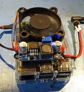
Position the regulator as shown. The input pads should be same side of the case as the Pi's power connector.
If you're also fitting a fan, position it as shown. Note that you'll at best be only able to use three of the fan's four screw holes as the case cut outs are often in the way. Also note that this fan mod is unsuitable if you need to use the camera or display connectors (unless you use a novel wiring routing).
Ensure the regulator's mounting hole nearest the edge of the case is positioned above the gap between the Pi's two USB socket stacks (so the mounting screw doesn't foul - see step 4 for a photo of the mounted regulator where you can see where the screw is positioned).
Use a fine permanent marker to mark the position of the two regulator mounting holes on the case and, if wanted, the fan mounting holes and a hole for the fan airflow.
Step 3: Drill the Case

Take the top of the case and turn it upside down onto a piece of wood for support.
Use a fine (1.5mm) drill to drill a pilot hole where marked in the last step.
Use a 2.5mm drill to widen one of the holes and check the selected self-tapping screw can be screwed in without too much effort. Widen the hole size if necessary.
Once you're happy with the hole size, drill out the other one to suit.
Step 4: Mount the Regulator
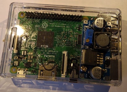


Mount the regulator using the stand-offs and self tapping screws as shown in the photographs. Note the position of the screw between the two USB connector stacks.
Step 5: Wiring


Solder the equipment wire to the dc power supply socket and insulate with the heatshrink sleeve as shown. Assuming you've got a standard power supply where the positive voltage is on the inner connector, solder the red wire to the short tag and the black wire to the long tag (this assumes the long tag is connected to the outer of the socket - use a multimeter to check though). If the polarity is reversed, solder the red and black wires to the opposite tags.
Push the other end of the wires under the regulator board and solder to the regulator's input pads as shown (again, red to +ve, black to -ve).
If you've got a sacrificial micro USB lead, cut it so you've got around 180mm of cable connected to the micro USB end. Using a fine piece of wire and your multimeter in resistance mode, identify which wire is connected to the positive and negative contacts of the micro USB connector (see above for a diagram). Red and black are the usual colours used in USB leads for +ve and -ve connections (sometimes marked 'Vcc' and 'Gnd' respectively). Cut the other wires (usually white & green) short. Slip a piece of heatshrink sleeve over them and the outer sheath and shrink in place.
Push the cut end under the regulator, strip and tin the red & black wires and solder them to the regulator's +ve & -ve output pads respectively.
If you're being brave (like wot I woz), make up your own USB lead using a bare connector. Solder the wires to the USB connector pads as shown, cover the joints with a thin layer of hot glue and when set, slip the 1/4" heatshrink sleeve over as shown.
Shrink the sleeve with the heatgun and the glue will act as a strain relief (hopefully!).
As above, slip the other ends of the wire under the regulator and solder to the output pads.
It's always a good idea to double check the polarity of your connections - use the multimeter and some thin wire to verify the USB pins are wired correctly to the regulator.
Step 6: Setting the Voltage


Before plugging the output of the regulator into the Pi, the output voltage needs setting.
Connect the power supply to the regulator dc input socket and switch it on. There's a blue LED on the regulator which should light immediately. If it doesn't and/or there's a whiff of smoke, disconnect and (if you're me) hang your head in shame. You may get away with it but if there's been some smoke it doesn't augur well. Carefully check your wiring, rectify and try again. Hopefully the LED has come on though...
Using a small screwdriver, adjust the potentiometer on the regulator (the blue box with a brass screw on the top) until the multimeter reads a tad under 5.1v. Anticlockwise reduces the voltage and it often takes more turns than you expect for the voltage to change - don't despair if it takes a few turns to see an effect.
Switch off the power supply and connect the output of the regulator to the Pi. You're ready for action!
Step 7: Part 2 - Adding a Cooling Fan and Heatsinks - Tools and Parts


Parts:
- 12v dc 0.12A 50mm x 50mm x 10mm sleeve bearing fan (eBay, multiple sellers)
- 3-off 15mm 2.8mm OD self-tapping screws (junk box)
- 2-off solid copper self-adhesive heat sinks for Raspberry Pi (eBay, multiple sellers)
Tools:
- Fret saw or electric Dremel-type tool with a burr-type cutter
- 1.5mm and 2.5mm drill bits and drill
- Soldering iron and solder
- Wire cutters and stripper.
- Hot glue gun (to hold the heat sinks in place)
Step 8: Cutting the Holes for the Fan


Using the marks on the case made in step 2, drill the three mounting holes in the same manner as for the regulator (ie) drill pilot holes with the 1.5mm drill and widen one of the holes with the 2.5mm drill. Test the fit of the self-tapping screws and if all is well, drill out the other two holes. Otherwise, widen the holes as necessary.
Using the fret saw or Dremel alternative, cut away the plastic hole to allow the fan airflow. Clean up the edges with a file if necessary (if my experience is anything to go by, using a power tool inevitably creates melted plastic which is a pain to clean up - hence my preference for a fret saw).
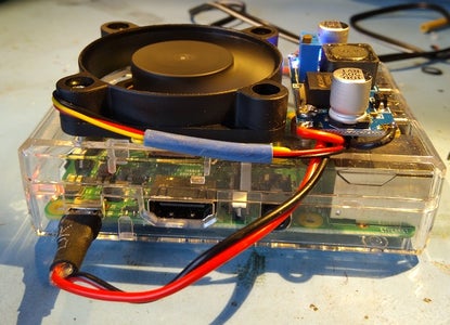
Offer up the fan to the mounting holes and carefully screw in the self-tappers. The fan should be mounted with the label side down, so the airflow is directed into the Pi. I would also orientate it so the wiring is not immediately adjacent to the regulator so you've got some slack wire to play with.
Spin the fan manually to check there's nothing catching.
Step 9: Wiring the Fan

My experience is that all but one fan of the type in the parts list started on its own when powered from 5v dc. In that case I found that running the fan from 12v dc for around five minutes loosened it up and it was thereafter fine on 5v. However, different manufacturer's fans may behave differently, so you may have to manually start the fan going - it should then be OK and continue to run. If this isn't the case, you still have the option of wiring the fan to the input of the regulator as long as this voltage is 9v to 12v and you can accept the noise increase.
Cut off the fan connector leaving enough wiring to reach the regulator. You can cut the yellow wire further back as it's not used in this type of application. Use a small piece of sleeving as shown to insulate it and keep it out of the way. Route the fan wiring under the regulator and solder to its output pads (red to positive, black to negative).
Step 10: Adding the Heatsinks


There's quite a bit of information on the internet about where (and when) to add heatsinks to Raspberry Pis. The steps below are my personal take.
As far as I can gather, the advice via the Raspberry Pi Foundation is you don't really need to add heatsinks to any model of Pi unless you're overclocking them. However, I've found that Pi 3 gets rather hot when attempting to play H265 videos and if not cooled can throttle back in an act of self-preservation.
Under these circumstances, the Broadcom SoC (the big chip on the upper surface of the Pi) gets the hottest, so that's worth heatsinking. Following some advice which I can't find the source of at the moment, I also heatsink the RAM chip on the underside. I don't bother with the smaller LAN chip as it doesn't seem to get that hot.
So, to business - peel off the cover strip from the heatsink and carefully position it on top of the SoC chip. Using the hot glue gun, carefully add a couple of blobs of glue either side of the heatsink as shown. I use a lot of my Pis on their sides, so after some time the heatsinks slide off - the glue helps prevent this. To date the glue hasn't softened sufficiently in use to lose integrity (it melts at around 120°C, so it shouldn't!)
The procedure for mounting a heatsink on the RAM chip is the same except you'll have to cut away some of the grill in the underside of the case to allow enough space. Note that it won't poke out past the boundary of the case.
Step 11: There Is No Step 11.
...and that's that.
I hope this Instructable proves useful and/or informative.
If you spot any errors etc. please let me know and I'll gladly edit accordingly.


