

Introduction: Raspberry Pi Push Button With LEDs Bare Metal


This is my second tutorial on programming the raspberry pi 3 bare metal! Check out my first one here.
Last time I showed you how to create an operating system image for the raspberry pi 3 that blinked a single led, in this tutorial I will show you how to put together a row of leds and make them blink in sequence. I will also introduce you to using a push button as input. The button will control in which direction the leds flash. Check out the gifs above for an example.
Step 1: Materials

For this project you will need
- Raspberry pi 3
- seven leds
- seven 220 ohm resistors
- one 10k ohm resistor
- one push button
You will also need a computer setup for working with the raspberry pi 3 in a bare metal fashion. Check out my previous instructable to learn how to setup an environment for working with the pi bare metal.
This project will probably take about 3-4 hours from start to finish.
Ok, let's get started!!!
Step 2: Circuit


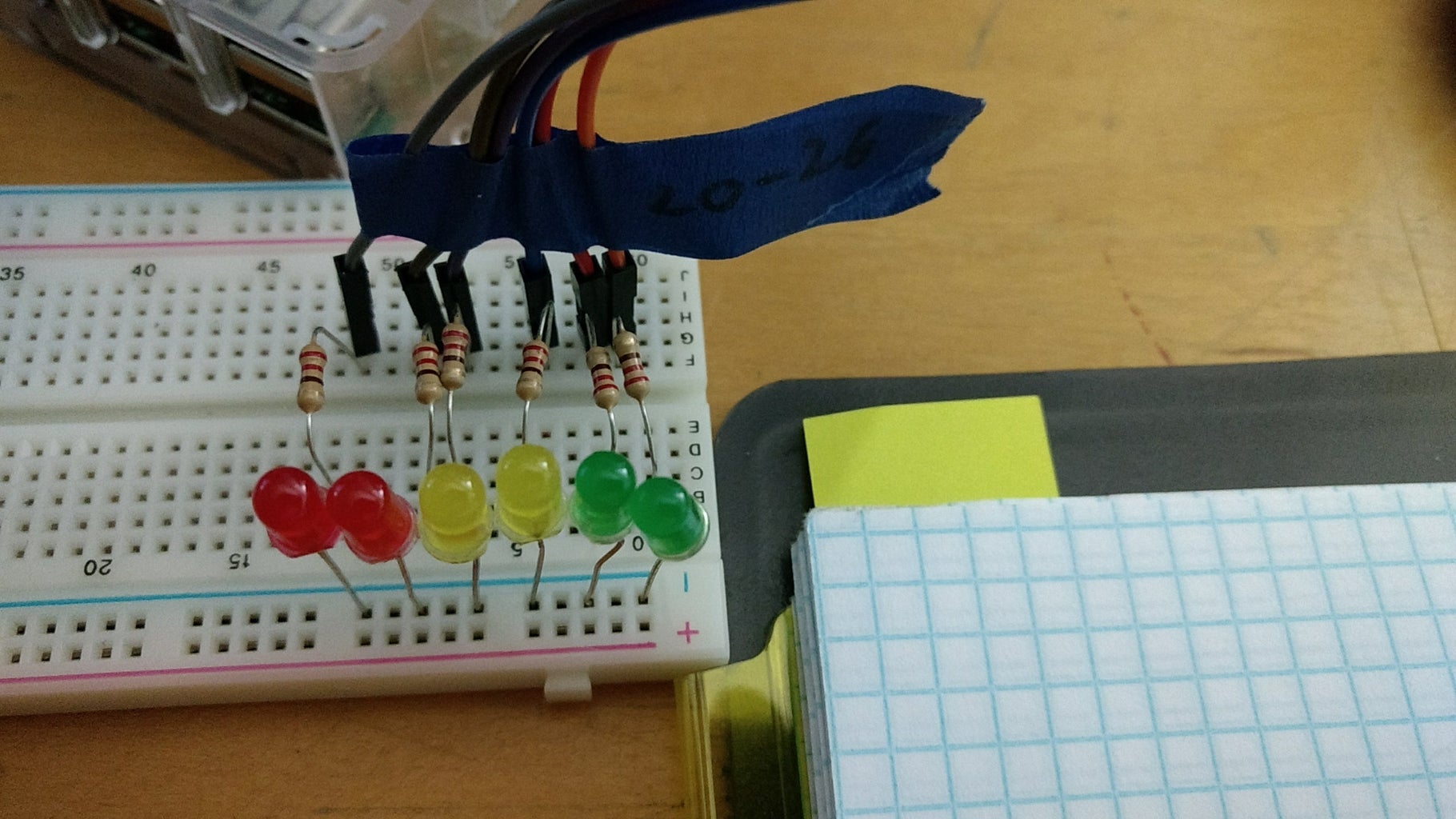
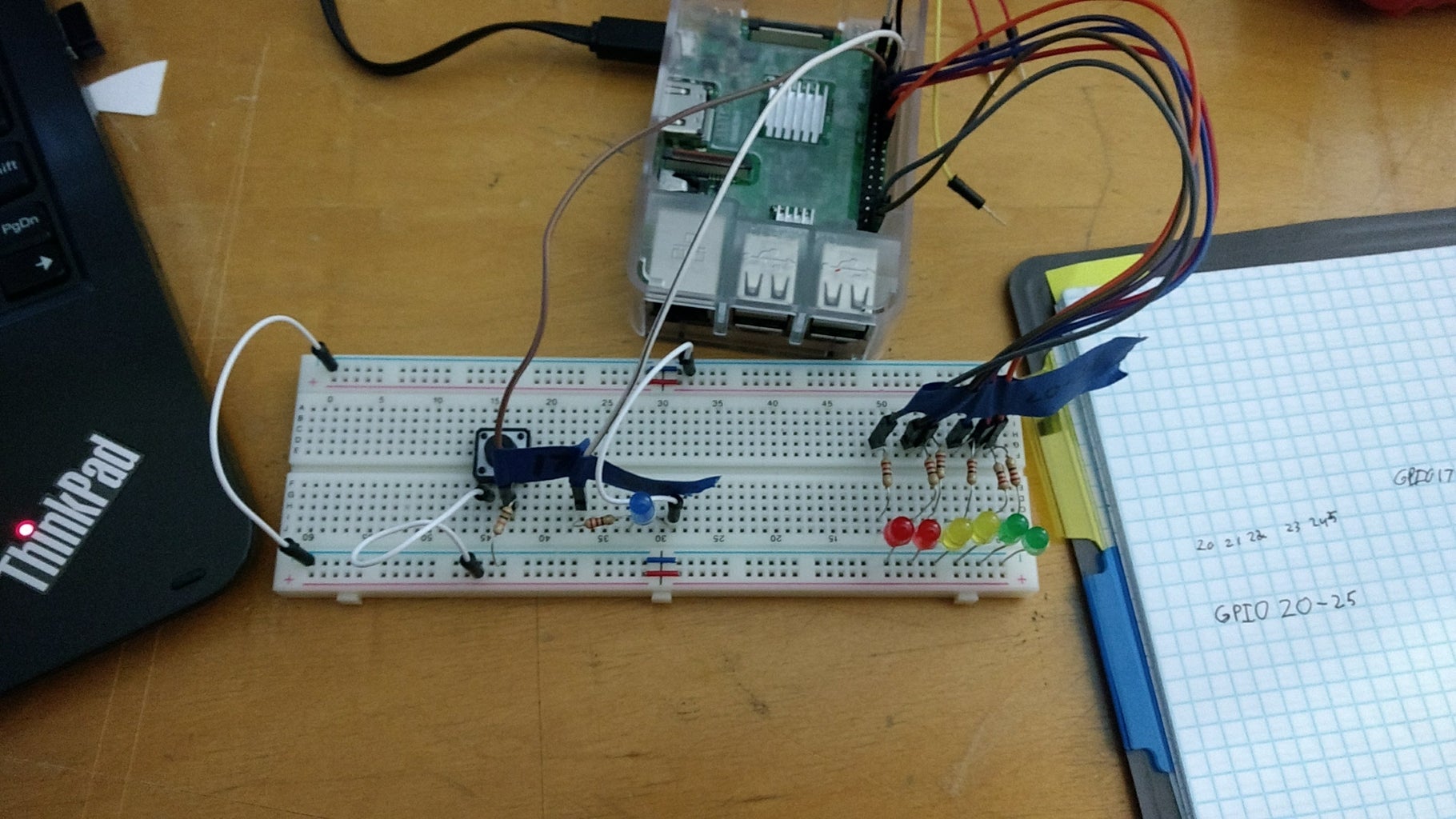

To build this we need a row of 6 leds connected to GPIO 20-25 respectively. We also need an indicator led connected to GPIO 27. This led will indicate to us whether or not the button has been pressed. Finally, we need to connect the button. One side of the button will be connected to 3.3v and the other to a pulled down pin. We will use GPIO 17 to be connected to the button. GPIO 17 will be our input pin. GPIO 17 is connected to a 10k ohm resistor that is connected to ground(GND). We do this to make sure that GPIO 17 is always set to low. If it is not then there is a chance that the pin could waiver between high and low giving us random results. To avoid this we pull the pin down to 0v with a resistor with large resistance.
Setting the circuit up on a breadboard is a simple process. Follow the circuit diagrams above. Connect the short side of an led to GND and the longer side to a 220 ohm resistor. Repeat this for 5 other different leds. You should end up with a total of six leds wired this way. Starting with one end, connect the first led's positive side to GPIO 20 and then connect the next pin to GPIO 21, etc... The last led should be connected to GPIO 25.
For the indicator led connect an led's short end to GND and long end to a 220 ohm resistor and connect the resistor to GPIO 17.
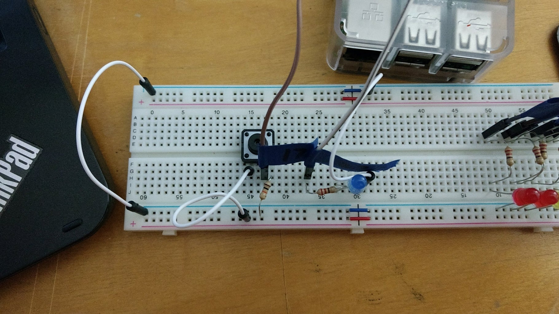
Attach the push button to the breadboard. There are four connections on the push button I am using. We will only use the bottom two. Connect one end to the positive rail and the other to a 10k ohm resistor. Connect GPIO 17 to the 10k resistor. When the button is pressed it connects GPIO 17 to the positive rail setting the pin high.
Connect a 3.3v pin to the positive rail and connect a GND pin to the negative rail.
Finally connect both positive rails and negative rails together so that both sides can be used.
Step 3: Code:Intro

The coding part builds off of what was already learned in the previous blinking light project.
Two new things in this project are that we setup stack frame use so we can simulate high-level functions, and we setup a wait function that uses the system clock to wait a specific amount of milliseconds.
The stack is a common programming structure. It is essentially a sequence of addresses that can be used to temporarily store things. A stack has two basic features
- you can push an item onto the top of stack
- and you can pop an item off the top of the stack
Stacks can be setup in different variations, but for this project we will stick to the default configuration. When you push something onto the stack it is put on top. When the next thing is pushed onto the stack the new item becomes the top and the old item sits below it. Hopefully, you have worked with stacks before, if not there are plenty of more in-depth explanations online. Luckily, Arm has a push and pop instruction so using the stack is easy in assembly.
The second thing we will explore is accessing the system timer so we can delay our program for a precise amount of time.
Step 4: Code:Stack/ Stack Frame

Setting up the stack to use is as simple as one line of code. Because of how the linker is set up (kernel.ld) all of our code is inserted after 0x8000 when we compile it. So we need to move this value into the sp register.
- mov sp,#0x8000
Add this to the top of your code and using the stack shouldn't be a problem.
Now onto the stack frame. The stack frame is basically when we set aside part of the stack to use for procedure calls. This allows us to implement features that high level languages like java and c++ use. These languages use the stack to keep track of function calls. We can do the same thing in assembly.
Stack Frame:
To emulate function calls as high level languages do we will preserve the registers we want to use by placing them on the stack, then we can also set aside local memory in the stack if we need it for variables. At the end of the function, we have to destroy the stack frame and reset the stack to the way it was before.
In general, if the function needs to return anything it should be placed in r0.
If the function accepts arguments they should be placed on the stack right before the branch to the function.
Stack Frame: SETUP
We begin the function by setting up the stack frame.
- push {r7,lr}
- mov r7,sp
- push {}
- ldr ,[r7,#8] @first argument is at an offset of #8 from r7
Then we end the stack frame by cleaning it up.
- pop
- pop {r7,lr}
This process lets us call functions without having to change any registers. It also allows to call functions within functions because the stack frame will always preserve the lr so multiple level of function calls are allowed.
=======================================
stack frame visual
=======================================
0x0 |                                    <=sp
---------------------------------------
0x4 |
---------------------------------------
0x8 |
---------------------------------------
0x12|
---------------------------------------
0x16|
---------------------------------------
0x20|
---------------------------------------
0x24|
---------------------------------------
0x28|
=======================================
Example Function with one argument.
_______________________________________
push {r1}    @argument r1=0x1234
b ex_func
======================================= stack frame visual ======================================= 0x0 | 0x1234 <=sp The argument is pushed onto the stack --------------------------------------- 0x4 | --------------------------------------- 0x8 | --------------------------------------- 0x12| --------------------------------------- 0x16| --------------------------------------- 0x20| --------------------------------------- 0x24| --------------------------------------- 0x28| =======================================
ex_func:
    push {r7,lr}
    mov r7,sp                            @r7 will equal 0x8
=======================================
stack frame visual
=======================================
0x0 | 0x1234                            The argument is pushed onto the stack
---------------------------------------
0x4 | lr
---------------------------------------
0x8 | r7                                <=sp
---------------------------------------
0x12|
---------------------------------------
0x16|
---------------------------------------
0x20|
---------------------------------------
0x24|
---------------------------------------
0x28|
=======================================
push {r1-r3} @using r1,r2,and r3 so we preserve them
=======================================
stack frame visual
=======================================
0x0 | 0x1234 The argument is pushed onto the stack
---------------------------------------
0x4 | lr
---------------------------------------
0x8 | r7
---------------------------------------
0x12| r3 saved register
---------------------------------------
0x16| r2 saved register
---------------------------------------
0x20| r1 <=sp saved register
---------------------------------------
0x24|
---------------------------------------
0x28|
=======================================
pop r1,[r7,#8] @remember r7=0x8, the old sp. To access the argument at 0x0 we need to go up by 8
@thats why we do [r7,#8] which is the same as putting the value at 0x0 (0x1234) into r1sub sp,sp,#8 @moves sp down to create local memory ======================================= stack frame visual ======================================= 0x0 | 0x1234 The argument is pushed onto the stack --------------------------------------- 0x4 | lr --------------------------------------- 0x8 | r7 --------------------------------------- 0x12| r3 saved register --------------------------------------- 0x16| r2 saved register --------------------------------------- 0x20| r1 saved register --------------------------------------- 0x24| empty --------------------------------------- 0x28| empty <=sp =======================================
To end the function we need to move the value to be returned if any into ro
mov r0,<some value> @return
Then we need to undo the stack frame
Get rid of local memory created
add sp,sp,#8
=======================================
stack frame visual
=======================================
0x0 | 0x1234                            The argument is pushed onto the stack
---------------------------------------
0x4 | lr
---------------------------------------
0x8 | r7
---------------------------------------
0x12| r3                                saved register
---------------------------------------
0x16| r2                                saved register
---------------------------------------
0x20| r1                                 <=sp saved register
---------------------------------------
0x24| empty
---------------------------------------
0x28| empty
=======================================
Replace saved registers
pop {r1-r3}
=======================================
stack frame visual
=======================================
0x0 | 0x1234                            The argument is pushed onto the stack
---------------------------------------
0x4 | lr
---------------------------------------
0x8 | r7                                <=sp
---------------------------------------
0x12| r3
---------------------------------------
0x16| r2
---------------------------------------
0x20| r1
---------------------------------------
0x24| empty
---------------------------------------
0x28| empty
=======================================
Replace r7 and link register
pop {r7,lr}
=======================================
stack frame visual
=======================================
0x0 | 0x1234                            The argument is pushed onto the stack
---------------------------------------
0x4 | lr                                <=sp
---------------------------------------
0x8 | r7
---------------------------------------
0x12| r3
---------------------------------------
0x16| r2
---------------------------------------
0x20| r1
---------------------------------------
0x24| empty
---------------------------------------
0x28| empty
=======================================
Finally, we need to clean up after the argument add sp,sp,#4 ======================================= stack frame visual ======================================= 0x0 | 0x1234 <=sp --------------------------------------- 0x4 | lr --------------------------------------- 0x8 | r7 --------------------------------------- 0x12| r3 --------------------------------------- 0x16| r2 --------------------------------------- 0x20| r1 --------------------------------------- 0x24| empty --------------------------------------- 0x28| empty ======================================= mov pc,lr Return
Notice that nothing is overwritten in the stack. We simply move the stack pointer back to it's original place.
Step 5: Code: System Timer


To setup a delay using the system timer, I wrote this in a separate file so I could use in future projects as well. To do this we basically need to access the timer and get the initial time stamp. Once we have that, we will again access the time stamp. We will subtract the second time stamp from the initial one and compare it to the desired value.
The algorithm is fairly simple, the hard part is accessing the right registers.
- The base address for the timer is 0x3f003000
- The offset for the lo word of the timer is 0x4
- The offset for the high word of the timer is 0x8
Try writing your own wait function! Attached is my code if you need a reference.
Attachments

Step 6: Code:Getting Input
For this project, I used the GPLEV0 register. Essentially it holds the state for pins 0-31. We are using GPIO 17 for input. To set this pin to input we must access the FSEL1 register and clear the three bit dedicated to GPIO 17.
- GPLEV0 offset 0x34
- FSEL1 offset 0x04
- Mask to set GPIO 17 to input 0xFF1FFFFF
We also need to set bits 20-27 to output.
- FSEL2 offset 0x08
- Mask to set 20 through 27 to output 0x249249
And because we are using output we also need to access the GPSET0 register to turn on pins and the GPCLR0 register to turn off pins
- GPSET0 offset 0x1c
- GPCLR0 offset 0x28
And since the wait function is in micro-seconds here are a few values you can give it in a more reasonable time frame.
- half a second 0x7a120=500,000 micro seconds=1/2 second
- quarter second 0x3d090=250,000 micro seconds=1/4 second
- eighth of a second 0x1e848 =125,000 micro secons=1/8 second
Ok, let's start coding!
b main
.section .text
main:
mov sp,#0x8000<br>
The code above setups our code so it will run properly.
.equ BASE_ADDR,0x3f200000     @Base address<br>.equ GPFSEL0,  0x0
.equ GPFSEL1,  0x04        @FSEL1 register offset | use to select GPIO 10-19 and set input/output/alt func
.equ GPFSEL2,  0x08        @FSEL2 register offset | use to select GPIO 20-29 and set input/output/alt func
.equ GPSET0,   0x1c        @GPSET0 register offset| use to set GPIO's logic level high(3.3v)
.equ GPCLR0,   0x28        @GPCLR0 register offset| use to set GPIO's logic level low(0v)
.equ GPLEV0,   0x34        @GPIO level offset     | use to read current level of pin(on/off)[high/low]{3.3v/0v}
Next I setup the address of the base address and the offsets we will be using.
.equ CLEAR_BITS21_23,0xFF1FFFFF @mask to clear bits 21 through 23 | use to set GPIO 17 to input
.equ SET_20_27,0x249249        @mask to set bits 20 through 27   | use to set GPIO 20-27 to output
.equ SET_BIT27,0x8000000    @mask to set bits 27   | use to set GPIO 27 to high(3.3v) or low(0v) GPIO 27 is indicator light
.equ half_second, 0x7a120    @hex value for half a second in microseconds
.equ quarter_second, 0x3d090    @hex value for quarter of a second in microseconds
.equ eighth_second,0x1e848    @hex value for eigth of a second in microseconds
Here I setup some helpful symbols I will be using later.
base .req r1            @Sets symbol base to refer to r1: can use base and r1 interchangeably base<=>r1<br>ldr base,=BASE_ADDR        @base = 0x3f20000, load base with the base address of peripheralsoffset .req r2            @Sets symbol offset to refer to r2: can use offset and r2 interchangeably offset<=>r2
mask .req r3            @Sets symbol mask to refer to r3 mask<=>r3
i .req r4            @Sets symbol i to refer to r4 i<=>r4
j .req r5            @Sets symbol j to refer to r5 j<=>r5
return .req r0            @return <=> r0
For readability's sake, I setup some symbols for the register's purpose.
@=================================================<br>@Set gpio 17 to input
@=================================================
ldr offset,=GPFSEL1
ldr mask,=CLEAR_BITS21_23
str mask,[base,offset]
To set this pin to input, first I get the appropriate offset and then I load the mask; finally, I write the mask back to the register.
@=================================================<br>@Set gpio 20 through 27 to output
@=================================================
ldr mask,=SET_20_27
ldr offset,=GPFSEL2
str mask,[base,offset]
I do the same thing as I did for input but use a different offset and mask.
@=================================================<br>@Input Loop Repeats forever:
@1. waits a little
@2. checks input state(GPIO 17)
@3. turns off/on indicator depending on input state
@    1. loop up through row of leds
@    2. or loops down through leds depending on input state
@4. returns to input loop
@=================================================
Next, I start the main program loop. I start by describing what I want the program to do.
input_loop:<br>    mov r0,#30000
    bl Wait            @wait 30,000 microseconds
I start the loop with a small wait value.
mov mask,#17        @load args for proc<br>push {mask}        @ push onto stack
bl getInput        @get input for pin                 @result in r0
Here I am checking pin 17's state with a function that will return the state of a specified pin in r0. All of my functions will be listed at the end.
cmp r0,#1        @compare r0 to #1<br>beq turn_on_indicator @if pin is off turn on indicator
bne turn_off_indicator@if pin is on turn on indicator
b input_loop
I check the return value and then branch into a function that will either turn on the indicator light and loop up or turn off the indicator light and loop down.
If the button is pressed it connects GPIO17 to 3.3v so it is set high. So the if the button is pressed the input function returns 1, thus the indicator is turned on and the led's loop up, turning on from GPIO20 to GPIO 26.
So that is essentially it. Next, I will introduce the functions that are called in the input_loop.
Step 7: Code:Function Definitions
First off, we have the get input function.
@=================================================<br>@Returns State of Input Pin(GPIO 17)
@ARGUMENTS:1
@number of pin
@Reads state of pin from GPLEV0
@and returns it in r0
@=================================================
 getInput:
    push {r7,lr}
    mov r7,sp
    push {r1-r5}
@--------Set up stack frame
    ldr r4,[r7,#8]
@--------For readability
    argument .req r4
    result .req r5
@--------get first arg
    mov mask,#1
    lsl mask,argument        @create mask based on argument

    ldr base,=BASE_ADDR    @addr of base peripherals
    ldr offset,=GPLEV0        @GPLEV holds pin states
    ldr result,[base,offset]        @access GPLEV0
    tst result,mask        @cmp input pin to 1
    moveq r0,#0        @if pin state is
    movne r0,#1        @if pin state is
@--------
    .unreq argument
    .unreq result
@------Destroy stack frame
    pop {r1-r5}
    pop {r7,lr}
    add sp,sp,#4        @clean up argument on stack
    mov pc,lr        @return
My function has one argument, the number of the GPIO pin. The function uses the pin number to create a mask to test the bit in GPLEV0. tst performs a logical "and" and sets flags. If the and returns true the zero flag is not set.
- r1:0000_1000
- r2:0000_1000
- tst r2,r1
- result: zero flag not set
The result is returned in r0.
@=================================================<br>@turns on indicator light
@=================================================
turn_on_indicator:
    ldr offset,=GPSET0
    ldr mask,=SET_BIT27
    str mask,[base,offset]
    b loop_up_set        @if indicator light is on branch to loop_up
@=================================================
@turns off indicator light
@=================================================
turn_off_indicator:
    ldr offset,=GPCLR0
    ldr mask,=SET_BIT27
    str mask,[base,offset]
    b loop_down_set        @if indicator light is off branch to loop_down
Next, I have two functions that turn on the indicator and one that turns off the indicator. When the indicator is turned on the function will branch and loop up through the GPIO pins. When the indicator is off, the function will branch and loop down through the GPIO pins.
@=================================================<br>@Setup looping variable i and j
@if going down sets j to 26 and loops to 20
@if going up set i to 20 and loops up to 26
@=================================================
loop_down_set:            @set up parameters for looping down
    mov j,#26
    b loop_down
loop_up_set:            @ set up parameters for looping up
    mov i,#20
    b loop_up
@=================================================
@Loops through Gpio pins and turns them on and off
@Loops from GPIO 20 to 26
@=================================================
loop_up:
    mov r0,i        @args to turn on pin
    bl turn_on        @turn on  pin
    @---------
    ldr r0,=eighth_second    @wait for an eigth of a second
    bl Wait
    @---------
    mov r0,i        @args to turn offf pin
    bl turn_off        @turn off pin
    @---------
    cmp i,#25        @check for end of loop
    beq input_loop        @go back to input loop if at end
    add i,i,#1        @increment counter
    b loop_up        @loop back if not at end
@=================================================
@Loops through Gpio pins and turns them on and off
@Loops from GPIO 26 to 20
@=================================================
loop_down:            @same as loop_up but decrements
    mov r0,j
    bl turn_on
    @---------
    ldr r0,=eighth_second
    bl Wait
    @---------
    mov r0,j
    bl turn_off
    @--------
    cmp j,#19
    beq input_loop
    sub j,j,#1
    b loop_down
The first two functions setup the loop up or loop down functions. They just make sure the counters are set to the right number before the loop begins. The loop_up and loop_down functions do essentially the same thing as each other. One loops up through the pins starting with GPIO 20 and ending with GPIO 26 and the loops down through the pins starting with GPIO 26 and ending with GPIO 20.
The loop position i or j is moved into r0 and then the turn_on function is called. This turns on a pin based on the number passed into r0. Then the loops waits an eighth of a second before turning off the pin and incrementing or decrementing the counters.
@=================================================<br>@Turns on GPIO Pin
@Accepts one argument:
@    arg1=>r0: pin number to turn on
@=================================================
turn_on:
    @turns on led
    @accepts pin number to turn on from pin 0-31
    ldr offset,=GPSET0
    mov mask,#1
    lsl mask,r0
    str mask,[base,offset]
    mov pc,lr
@=================================================
@Turns off GPIO Pin
@Accepts one argument:
@    arg1=>r0: pin number to turn off
@=================================================
turn_off:
    @turns off led
    @accepts  pin numnber to turn off from pin 0-31
    ldr offset,=GPCLR0
    mov mask,#1
    lsl mask,r0
    str mask,[base,offset]
    mov pc,lr
turn_on and turn_of functions.
Step 8: Putting It All Together.
Now that you have written all of your code files, you need to generate a binary kernel.img. I setup a simple makefile that spits one out. Just download it and change the code variable on line 4 to the names of your files.
If you are having trouble getting your code to work download and compile my code and put the kernel.img onto the pi. If it works then there might be a problem with your code if it doesn't go back to the circuit step and try rebuilding your circuit.
A

Participated in the
Microcontroller Contest


