

Introduction: Raspberry Pi Robot Car

The goal of the project is to create a simple 4-wheeled Raspberry Pi Robot Car. The process for completing this is to connect motors, a Raspberry Pi, and a battery pack to a L298n H-bridge motor board through wires, place that circuit in a designed car frame, and to program the raspberry Pi with Python.This project is originally by sentdex in his YouTube series "Raspberry pi with Python for Robotics", https://www.youtube.com/watch?v=LlFkybEQFFA&list=PLQVvvaa0QuDeJlgD1RX9_49tMLUxvIxF4&feature=share
Required Material:
Raspberry Pi
L298n Stepper Motor Driver Controller Board Module
Edimax EW-7811UN 9V (wifi dongle)
Battery pack 5200 BW – Universal Power Bank
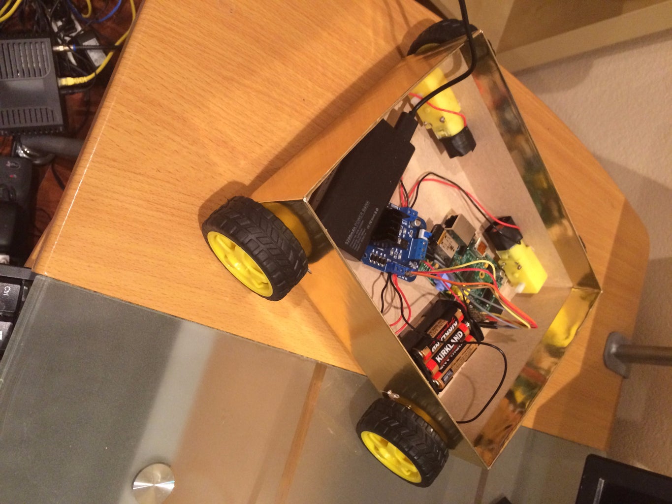
Robot car chasis (shoebox)
4 motors
4 wheels
Screws
Required Equipment:
Wire strippers
Wire cutters
Screw driver
Electrical tape or soldering iron
Step 1:
Take two wires and strip off both ends of each one. Connect the black wire to the left side of one of the motors and the red wire to the right side. Then place the black wire connected to the left side of the motor into Output 1 on the H-bridge and the red wire connected to the right side of the motor into Output 2 on the H-bridge. Make sure the wires are placed tightly into the outputs because they come loose easily.
Step 2:
Take your battery pack and connect the red wire into the VCC slot and the black wire in the GND slot, both found on the H-Bridge. Then take some female to male jumper wires and connect the female ends to GPIO pin 2 (5V) and GPIO pin 6 (Ground) on your Raspberry Pi and the male ends for into the 5V slot and GND slots on the H-bridge respectively. Once again make sure the connection is tight.
Step 3:
Step 3: Take 4 female to female jumper wires and connect one of their ends to GPIO pin 15, 13, 11, and 7 . Take the other ends and connect them respectively to Inputs 1, 2, 3, 4 on the H-bridge.
Step 4:
Now we must see if everything has successfully connected by running a test code. In order to code we must connect the Raspberry Pi to a monitor to display what is actually happening. This can be achieved by connecting the HDMI port of the Pi to the HDMI port of the monitor. In my case, I used my TV as a monitor. Additionally we must give the Pi power by connecting it to a power supply. Connect one end of the power supply into an outlet and the other end into the micro usb port on the Pi. Then connect a keyboard and mouse to the USB ports on the Pi and you will be ready to code.
Step 5:
The first thing we have to do is get Rpi.GPIO on our Pi if it does not already have it. Run sudo apt-get install python.Rpi.GPIO. The next thing we should do is make a class (let's call it robotics) for all our codes. This can be achieved by doing mkdir robotics. Then we must do cd robotics to get into the class and then run sudo nano robot1.py (nano lets us edit the code, robot1.py is the name of the individual code). There then should be an empty space for the code. Enter this in:
import Rpi.GPIO as gpio
import time
gpio.setmode(gpio.BOARD)
gpio.setup(7, gpio.OUT)
gpio.setup(11, gpio.OUT)
gpio.setup(13, gpio.OUT)
gpio.setup(15, gpio.OUT)
gpio.output(7, True)
gpio.output(11, True)
gpio.output(13, False)
gpio.output(15, False)
time.sleep(0.5)
gpio.cleanup( )
After you enter the code, press Control and x to exit and then Y to save the code. You can run the code by typing in sudo python robot1.py. The motor should be moving for 0.5 seconds in response to this. If it is not working double check your wiring and/or code.
Step 6:
If the test code was successful, you can begin to connect the remaining three motors to H-bridge. Repeat the same process of connecting the wires to the motors in Step 1. Once one end of the wires are connected to their respective motors, begin placing them in the Outputs in the same way as the initial wires in Step 1. On the opposite side side of the H-bridge will be Outputs 3 (directly across Output 2) and 4 (directly across Output 1). In order to stagger the motors, place the black wires in the remaining two motors into Output 3 and the red wires into Output 4. Make sure the wires are tightly connected to the outputs.
Step 7:
Once the wires are connected you can begin to code the movement commands. Connect your Raspberry Pi to a monitor and begin to code. cd robotics again and once again test out the motors by running sudo python robot1.py . If everything is running you can begin to start with the forward and reverse commands. For all the movement commands we will place them in sudo nano robot2.py . For the forward command enter this code
import Rpi.GPIO as gpio
import time
def init():
gpio.setmode(gpio.BOARD)
gpio.setup(7, gpio.OUT)
gpio.setup(11, gpio.OUT)
gpio.setup(13, gpio.OUT)
gpio.setup(15, gpio.OUT)
def forward(tf):
init()
gpio.output (7, True)
gpio.output (11, False)
gpio.output (13, False)
gpio.output (15, True)
time.sleep(tf) '
gpio.cleanup()
forward(1)
Save and escape again.Test out the code by running sudo python robot2.py . All the wheels should move forward for a second. If it works, delete forward(1) and continue to the reverse code:
def reverse(tf):
init()
gpio.output (7, False)
gpio.output (11, True)
gpio.output (13, True)
gpio.output (15, False)
time.sleep(tf)
gpio.cleanup()
reverse(1)
Test it out once again to see if the motors actually move in reverse for a second. Now we can continue on to turning codes. Delete reverse(1) and then enter this for the turning left code:
def turn_left(tf):
init() 0
gpio.output (7, True)
gpio.output (11, True)
gpio.output (13, True)
gpio.output (15, False)
time.sleep(tf)
gpio.cleanup()
turn_left(1)
Repeat the process of testing and deleting, and then if successful, continue on to the turning right code:
def turn_right(tf):
init()
gpio.output (7, False)
gpio.output (11, True)
gpio.output (13, False)
gpio.output (15, False)
time.sleep(tf)
gpio.cleanup()
turn_right(1)
Repeat the process of testing and deleting, and then if successful, continue on to the pivot left command:
def pivot_left(tf):
init()
gpio.output (7, True)
gpio.output (11, False)
gpio.output (13, True)
gpio.output (15, False)
time.sleep(tf)
gpio.cleanup()
pinot_left(1)
Repeat the process of testing and deleting, and then if successful, continue on to the pivot right command:
def pivot_right(tf):
init()
gpio.output (7, False)
gpio.output (11, True)
gpio.output (13, False)
gpio.output (15, True)
time.sleep(tf)
gpio.cleanup()
pinot_right(1)
Repeat the process of testing and deleting, and if it turns out successful then you are done with all the movement codes.
Step 8:
Now that all movement codes have been made, we must add some sort of user control that enables us to control the car movements. To achieve this we must first get to the desktop feature on the raspberry Pi by entering startx. Once in the desktop, click on the bottom left icon and then go to Accessories and then to File manger. Once in File manager click on your robotics class, and the copy and paste robot2.py, renaming it to robot3.py . Then go to edit, then programming, and then finally IDLE, and you will be ready to start the code for user control.
Step 9:
Delete all the init( ) and the pivot_right(1). Go back to the top and below import time put import sys and under that put import Tkinter as tk. Once you complete that, enter this code under the pivot right one.
def key_input (event):
init( )
print ‘Key:’ , event.char
key_press = event.char
sleep_time = 0.030
if key_press.lower( ) == ‘w’:
forward(sleep_time)
elif key_press.lower( ) == ‘s’:
reverse(sleep_time)
elif key_press.lower( ) == ‘a’:
turn_left(sleep_time)
elif key_press.lower( ) == ‘d’:
turn_right(sleep_time)
elif key_press.lower( ) == ‘q’:
pivot_left(sleep_time)
elif key_press.lower( ) == ‘e’:
pivot-right(sleep_time)
else:
pass
command = tk.Tk( )
command.bind (‘<KeyPress>’, key_input)
command.mainloop( )
With this, specific letters on the keyboard can control specific movements of the car. To test it on click on the Lx terminal program and enter sudo python robot3.py and a small screen should appear. Click on the screen and enter in the letters, w, a, s, d, q, e, to see if they actually move the motors. If successful we can begin to move on to the car frame.
Step 10:
For my project, I ended up using a shoebox as the car’s frame. Its provides enough space for the circuit and has an already made removable top. The only changes that need to be made are creating holes on the left and right sides of the box for the motors’ axle to stick out and for the screws that keep the motor in place. You must make specific measurements that are based on the positioning of the axle and screw holes of your own unique motors. After cutting holes for the motors, put the circuit in the box and screw in the motors to the sides and attach the wheels to the axles. With that you frame should be done.
Step 11:
Now we must find a way to access our Pi remotely. First, type in sudo apt-get install xrdp. Then, type in startx to get into desktop feature again. Once you are there, plug your wifi dongle into the raspberry Pi. Then press on the Wi-Fi config program, and then Scan. Find the network you want to connect to and connect to it. Then go into the LX terminal and type in sudo ifconfig. This will give you the IP address of your Pi. Once you have that, go to a remote device such a laptop or desktop computer and search for Remote Desktop connection. After you click it, enter in the Pi’s IP address to establish a connection between the two. Enter in the Pi’s username and password (pi and raspberry if you have raspbian) and then you will be able to access the Pi from your laptop. Run sudo python python3.py and you will be able to remotely move the car. With this step completed you should have a completed robot car.


