

Introduction: Raspberry Pi Stompbox Synth Module


The goal of this project is to put a Fluidsynth-based sound module into a stompbox. The technical-sounding term "sound module" in this case means a device that takes in MIDI messages (i.e. note value, volume, pitch bend, etc.) and synthesizes actual musical sounds. Put this together with a MIDI controller - which are legion, cheap, and often very cool (like keytars!) - and you have a synthesizer that you can mod and tweak endlessly, and design in a way that suits your playing style.
A broad overview of this project is that we take a small single-board linux computer (a Raspberry Pi 3 in this case), attach a character LCD, a couple pushbuttons, and a USB soundcard (since the Pi's onboard sound is not very good), and cram everything into a Hammond 1590bb stompbox (like those used for guitar effects) with some exterior connections for USB MIDI, power, and audio outs. Then we configure the internal software to run a program on startup that runs FluidSynth (an excellent, multi-platform, free software synthesizer), controls the LCD, and lets us change patches and settings using the pushbuttons.
I will not go into minute step-by-step detail on this build (there are plenty of hey-i-made-a-cool-raspberry-pi-case tutorials out there), but will instead try to focus on why I made various choices in the construction and design as I went. This way you can hopefully make modifications to suit your own purposes without getting stuck doing things that later turn out not to work.
UPDATE (May 2020): While this instructable is still a great place to start for a project like this, I've made a lot of improvements on both the hardware and software side. The latest software is FluidPatcher, available on GitHub - check out the wiki for lots of details on setting things up the Raspberry Pi. Check out my site Geek Funk Labs for continual news and updates on the SquishBox!
Supplies
This is a short list of (and explanation for) the more crucial components:
- Raspberry Pi 3 Computer - Any single board linux computer could work, but the Pi 3 has enough processing power to run Fluidsynth without any latency, and enough memory to load big soundfonts. The drawback is it has poor onboard sound, so you need a USB soundcard. The CHIP is an alternative I'm exploring (smaller footprint, better sound, but less memory/processor)
- Hammond 1590BB enclosure - I suggest buying one that is pre-powdercoated if you want color, unless painting stompboxes is something you're into. I browsed a lot of message boards but I think I don't have the patience or the right type of paint, because after two attempts my results are pretty so-so.
- USB Sound Card - You can find an appropriate one of these pretty cheaply. According to this lovely Adafruit tutorial (one of many), you should stick with one that uses the CM109 chipset for maximum compatibility.
- Character LCD - there are manydifferentplaces to get them, but the pinouts seem to be pretty standard. Make sure you get backlight so you can see your presets when playing out in the smoky clubs.
- Momentary stompswitches (2) - A little harder to obtain, but I got momentary instead of toggle so I could have more versatility. I can simulate toggle in software if I want that behavior, but this way I can also have different functions for short tap, long press, etc.
- Adafruit Perma-Proto Hat for Pi - This helped me get the LCD and other components connected to the Pi's expander port without taking up a lot of extra space. If I'd tried to use regular perfboard it would have had to stick out over the sides of the Pi for me to connect to all the necessary GPIO pins. The double-sided plating and matching mounting holes were very useful as well. In light of all this it was really the cheapest option.
- USB connectors - 1 B-type female for power, and two each of A-type male and female with which to make some skinny, flexible extender cables for internal connections.
- 1/4" audio jacks - I used one stereo and one mono. That way the stereo can be a headphone/mono jack, or just carry the left signal if the other jack is connected.
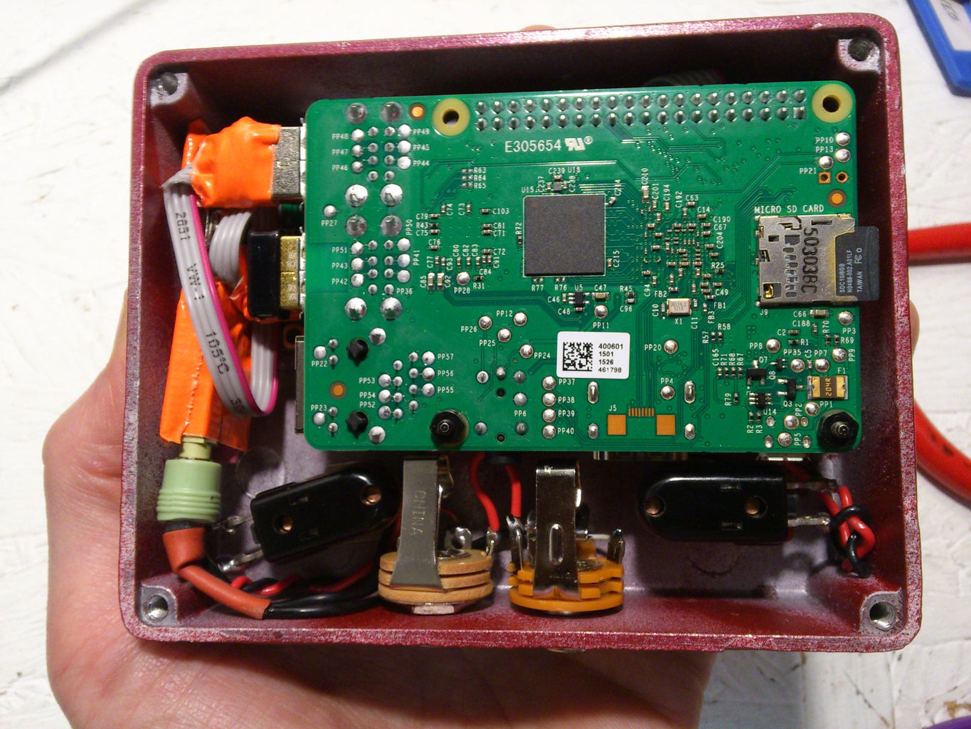
Step 1: Internal Electronics


We will connect the LCD and its associated components and the pushbuttons to the Pi Hat. Also, we will add a USB-B and USB-A jack to connect power and a MIDI device, respectively. We bring the USB-A port over because we need to use one of the Pi's USB ports to connect the sound card, which we want to have inside the enclosure, so we cannot have the USB ports flush with the side of the box. I used a USB-B port for power because I felt like it could take more punishment than the Pi's micro-USB power connector, plus I couldn't find a good orientation where the connector could be next to the edge of the box anyway.
You will need to use a knife to cut the traces between the holes where you will solder in the pins for the USB jacks. Just be careful not to cut any of the internal traces in the board connecting the other pins - or if you accidentally do (like me) reconnect them using jumper wire. The USB-B jack's Vcc and GND pins go to 5V and GND on the Pi's expander port, respectively. This way you can power your stompbox with a phone charger (assuming it has enough amperage - 700mA seems to work for me, but you may want more to be sure the USB port has enough juice to power your controller) and a USB A-B cable.
I find that lengths of ribbon cable work really well for connecting things with lots of pins without having too much wire spaghetti. I did this rather than soldering male headers into the LCD and then soldering it into the hat because I felt like I needed some freedom to position the LCD so I could get it centered nicely. The LCD should come with a potentiometer that you use to adjust the constrast - make sure you put this in a spot where it will not be covered by the LCD, so you can make a hole in the box to reach it and adjust the contrast once everything's assembled.
Consult the schematic for details on what gets connected where. Notice that the pushbuttons are connected to 3.3V - not 5V! The GPIO pins are only rated for 3.3V - 5V will damage your CPU. The USB-A jack gets connected to another strip of ribbon cable, which you can then solder to a USB plug which you'll connect to one of the Pi's USB ports for your MIDI controller. Cut any extra metal off the plug so it sticks out less, and use hot glue for strain relief - it doesn't have to be pretty since it will be hidden inside the box.
Step 2: Audio Output Wiring


No matter how tiny a USB sound card you find, it or its plug will likely stick out too far from the Pi's USB ports for everything to fit in the box. So, solder together another short USB connector out of some ribbon cable, USB plugs, and hot glue as shown in the picture above. My sound card was still a little too chunky to fit in the enclosure with everything else, so I popped the plastic off and wrapped it in some duct tape to keep it from shorting against things.
To get audio from the sound card to your 1/4" jacks, cut the end off a 3.5mm headphone or AUX cable. Make sure it has 3 connectors - tip, ring, and sleeve (TRS), as opposed to 2 or 4. The sleeve should be ground, tip is usually the right channel, and ring (the middle connector) is usually left. You could just connect tip and ring to two mono (TS - tip, sleeve) 1/4" jacks and be done with it, but you can get some more versatility with a tiny bit of extra wiring. Find a TS jack that has a third momentary contact, as shown schematically in the diagram above. Inserting a plug breaks this contact, so as you can hopefully tell from the diagram the left signal will then go to the TS jack if a plug is inserted, and to the ring of the TRS jack if no plug is inserted. In this way you can plug headphones into the stereo jack, a single mono cable into the stereo jack for a combined right/left (mono) signal, or a cable in each jack for separate right and left (stereo) outputs.
I connected the ground pins of the jacks to that of the cable coming from the sound card, so that everything in the box shares the same ground and I avoid the nasty buzz of ground loops. Depending on what you're plugged into, however, this may have the opposite effect - so you may want to include a switch to allow you to either connect or "lift" the ground on the 1/4" jacks.
Step 3: Preparing the Enclosure


This step covers cutting holes in the box for the screen, buttons, connectors, etc. and epoxying standoffs in the enclosure to mount the Pi hat.
Begin by placing all the components in the enclosure to make sure everything fits and is oriented the right way. Then, carefully measure and mark where you're going to make holes. When cutting round holes, I recommend starting with a small bit and working up to the size you need - it's easier to center the hole and less likely your drill will jam. Rectangular holes can be cut by drilling a hole in opposite corners of the intended opening, then cutting with a jigsaw to the other two corners. This thickness of aluminum actually cuts just fine with a jigsaw as long as you go gently. A square file is very helpful for squaring off corners of openings. Make the openings for the USB plugs a bit generous in case you have fat cables.
A two-stage epoxy (like the Gorilla Glue in the picture) works well to affix the standoffs for the hat to the metal enclosure. Scratch up the surface of the enclosure and the bottom of the standoffs a bit with steel wool or a screwdriver so the epoxy can get a better grip. I recommend attaching your standoffs to the Pi hat before gluing them down so you know they are positioned correctly - there isn't a lot of wiggle room here. I only used three standoffs because my LCD was in the way of the fourth. Mix up the two components of the epoxy, paste some onto the standoffs and clamp them in place. Avoid wiggling or repositioning the parts after any more than 10-15 seconds, or the bond will be brittle. Give it 24 hours to set up so you can continue working. It takes a few days to fully cure, so don't stress the bond unnecessarily.
Unless you want to make another hobby out of painting stompboxes, I suggest leaving the aluminum bare (not a bad look actually) or buying a pre-painted enclosure. Paint does not want to bond to metal. If you want to try it, sand everywhere you want paint to stick, use a good auto body primer spraypaint first, apply several coats of the color you want, then let it dry as long as possible. Seriously - the maniacs on the message boards suggest things like leaving it in direct sun for three months, or in a toaster oven set on low for a week. After sanding off the crinkled, peeling remains of my first paint job, my second attempt still gets chips and gouges from things like pens in my gig bag, and the finish can be dented with a fingernail. I decided to give in and went for punk style, using white-out marker for the lettering.
Step 4: Software Setup


Before you stuff everything into the stompbox and screw it up tight, you need to set up software on the Raspberry Pi. I suggest starting with a fresh install of the Raspbian OS, so get a recent copy from the Raspberry Pi Foundation site and follow the instructions there to image it onto an SD card. Grab a keyboard and screen or use a console cable to log in to your Pi for the first time, and get to a command line. To make sure you have the most recent software and firmware updates, enter
sudo apt-get update && sudo apt-get upgrade
sudo rpi-update
Next, you want to make sure you can use wifi to ssh to the Pi and make modifications once it's buttoned up inside the enclosure. First, turn on the ssh server by typing
sudo raspi-config
and going to "Interfacing Options" and enabling the ssh server. Now, add a wireless network to the pi by editing the wpa_supplicant.conf file:
sudo vi /etc/wpa_supplicant/wpa_supplicant.conf
and adding the following lines at the end:
network={
  ssid="your-network"
  psk="your-password"
}
Replace your-network and your-password above with values for whatever network you want the Pi to connect to by default - most likely your wifi router at home, or perhaps the hotspot on your phone or a laptop running in access point mode. Another alternative for connecting to your Pi is to set it up as a wifi access point, so that you can just connect to it no matter where you are. The interface I wrote below also allows you to pair another bluetooth device with the Pi, after which you can connect to it using serial-over-bluetooth.
To install FluidSynth, type
sudo apt-get install fluidsynth
The files attached to this step provide an interface between the stompbox controls and FluidSynth, and should be copied into the /home/pi directory. Here is a short explanation of what each file does:
- squishbox.py - A python script that starts and communicates with an instance of FluidSynth, reads input from the stompbox buttons, and writes information to the LCD
- config_squishbox.yaml - A configuration file in the (mostly) human-readable YAML format that stores settings and patch information for the squishbox program
- fluidsynth.py - A python wrapper that provides bindings to the C functions in the FluidSynth library, with many additional bindings added by me to access more of FluidSynth's functionality
- ModWaves.sf2 - A very small soundfont I provided to demonstrate the usage and power of modulators in the Soundfont format
Having a python script set up the FluidSynth process and handle all the button/LCD stuff works quite well - MIDI messages go directly to FluidSynth and the script only interacts with it when it needs to.
The python script needs a couple python libraries that are not installed by default. You can install them directly from the Python Package Index using the handy pip tool:
sudo pip install RPLCD pyyaml
Finally, you want the Pi to run the python script on boot. To make this happen, edit the rc.local file:
sudo vi /etc/rc.local
Insert the following line just before the final 'exit 0' line in the file:
python /home/pi/squishbox.py &

Step 5: Final Assembly


Before putting all the pieces into the box, it's a very good idea to plug everything in and make sure the software works, as demonstrated in the images above. Images 3-6 show all the individual parts and progressively how they fit into my box. The LCD is actually held in place by the wires pressing against it, but you could use some hot glue or add some more mounting screws if you don't like that. The orange duct tape on the box lid is to keep the Pi from shorting against the metal.
You may have to experiment and reconfigure to get things to fit. Snug is good - the less parts jiggle around in the box, the better. Heat does not seem to be an issue, and I haven't had any problems with wifi signal being blocked by the enclosure. Not pictured are some adhesive rubber feet (you can find them at a hardware store) on the bottom of the box to keep it from sliding around when you're having a stomp session.
Watch for unforseen bumping/squishing/bending when things are screwed together. One thing to check is that there is enough space for the 1/4" jacks when cables are inserted - the tips stick out a bit farther than the jack contacts. Also, in my build I mounted the Pi a bit too close to the edge of the box and the lip on the lid pressed down on the end of the SD card and snapped it - I had to file a notch in the lip so this wouldn't happen.
Step 6: Usage


The sound module I've described in these steps and running the software provided above is pretty usable and extensible out of the box, but many modifications/variations are possible. I will just briefly describe the interface here - I plan to continually update it in a github repository, where I will hopefully keep an updated wiki as well. Lastly, I will discuss how you can tweak the settings, add new sounds, and make your own modifications.
To start, plug a USB MIDI controller into the box's USB-A jack, a 5V power supply into the USB-B jack, and connect headphones or an amp. After a bit the LCD will show a "squishbox vxx.x" message. Once a patch number and name appear you should be able to play notes. Short taps on either button change the patch, holding either button for a couple seconds gets you into a settings menu, and holding either button for roughly five seconds gives you the option to restart the program, reboot the Pi, or shut the Pi down (N.B. the Pi does not cut power to its GPIO pins when it halts, so the LCD will never turn off. Just wait about 30 seconds before unplugging it).
The settings menu options are:
- Update Patch - saves any changes you've made to the current patch to file
- Save New Patch - saves the current patch and any changes as a new patch
- Choose Bank - the config file can have multiple sets of patches, this lets you switch between them
- Set Gain - set the overall output volume (fluidsynth's 'gain' option), too high gives distorted output
- Chorus/Reverb - modify the current set's reverb and chorus settings
- MIDI Connect - try to connect a new MIDI device if you swap it out while the program's running
- Bluetooth Pair - put the Pi in discovery mode so you can pair another bluetooth device with it
- Wifi Status - report the Pi's current IP address so you can ssh into it
The config_squishbox.yaml file contains information describing each patch, as well as things like MIDI routing, effects parameters, etc. It is written in the YAML format, which is a cross-language way of representing data that computers can parse but is also human-readable. It can get quite complex, but here I just use it as a way to represent a structure of nested Python dictionaries (associative arrays/hashes in other languages), and sequences (lists/arrays). I put a lot of comments in the sample config file and tried to structure it so that one can progressively see what each feature does. Take a look and experiment if you're curious, and feel free to ask questions in the comments. You can do a lot to change the sounds and functionality of the module just by editing this file. You can remotely log in and edit, or FTP a modified config file to the Pi, then restart using the interface or by typing
sudo python /home/pi/squishbox.py &
on the command line. The script is written to kill off other running instances of itself when starting so there won't be any conflicts. The script will spit out a few warnings on the command line when it runs as it hunts for MIDI devices to connect and looks in various locations for your soundfonts. It is not broken, this is just lazy programming on my part - I could catch them but I claim they are diagnostic.
When you install FluidSynth you also get the pretty good free FluidR3_GM.sf2 soundfont. The GM stands for general MIDI which means it contains "all" the instruments, assigned to commonly-agreed-upon preset and bank numbers so that MIDI players that play files using this soundfont will be able to find roughly the right sound for piano, trumpet, bagpipes, etc. If you want more/different soundsyou can findlots of free soundfontson the internet. Most importantly, the soundfont specification is widely available, is actually quite powerful, and there is a wonderful open-source editor for soundfonts called Polyphone. With this you can build your own soundfonts from raw WAV files, plus you can add modulators to your 'fonts. Modulators allow you to control many of the elements of synthesis (e.g. ADSR envelope, modulation envelope, LFO, etc.) in real time. The ModWaves.sf2 file I've included above provides an example of using modulators to allow you to map the filter resonance and cutoff frequency to a control change MIDI message (which can be sent by a button/slider on your controller). There is so much potential here - go play!
It's my hope that this tutorial sparks a lot of ideas and gives others a good framework to build their own unique synth creations, as well as supporting the continuing availability and development of good soundfonts, the soundfont spec, and great free software like FluidSynth and Polyphone. The build I've outlined here is neither the best nor the only way to put something like this together. On the hardware side, possible modifications might be a bigger box with more buttons, legacy (5-pin) MIDI input/output, and/or audio inputs. The python script can be modified (apologies for my sparse commenting) to provide other behaviors that might suit you better - I'm thinking of adding an "effects" mode to each patch where it will act like a real effects stompbox, toggling settings on and off. One could also add some additional software to provide digital audio effects. I also think it would work better to have the Pi run in wifi AP mode as described above, and then it could even provide a friendly web interface for editing the config file. Please feel free to post your own ideas/questions/discussion in the comments feed.
I want to give huge, mega props to the makers of FluidSynth and Polyphone for providing free, open-source software we can all use to make great music. I love using this thing, and you made it possible!

Participated in the
Box Contest 2017

Participated in the
Invention Challenge 2017


