

Introduction: Raspberry Pi Web Stream Kit - Part 1


Here is a simple, yet slightly ugly camera kit I put together to support school events, such as a FIRST LEGO League qualifying tournament. The purpose is to allow for a single drop in kit that will provide 4 web streams to an external computer. Nothing too hard, but I wanted a nice container to put it all together. The end result is a drop in box that needs external power and Ethernet (wired) and provides 4 USB connectors for some webcams.
For my deployment, I chose a .50 caliber ammunition can, found at my local Harbor Freight.
I'll first document the hardware. Then, for Part 2, I will document the raspberry pi webcam streaming portion. I'll probably need a part 3 for the OBS Studio side of things. All in due time
UPDATE (8/31/19): Part 2 is complete: https://www.instructables.com/id/Raspberry-Pi-Web-Stream-Kit-Part-2-Pi-Video-Stream/
Step 1: Prepping the Power Supply


Using the ammo can created a few issues, especially if I wanted to leave the can sealed. I didn't want to install a plug to accept the normal C13 connector (like your PC power cord). But I also wanted a power switch.
The power needs were for:
- Ethernet switch (wall wart DC convertor)
- Raspberry Pi's (USB power cables for all 4 Units).
The Trond Prime Mini (old version) provides exactly the needs with 2 AC ports, and 5 USB ports. (see photo)
The first ugly work is to create two holes in the ammo case (See photo)
- The power switch on the Trond
- Hole for the power cord
The switch was a simple circle. The power cord was created by creating the first hole and then reaming out the hole in each direction until the 3-prong plug would fit.
Each of the holes was covered with liquid rubber to prevent it cutting thru the cords or cutting me.
Step 2: Create Other Holes (E-net, USB)


The first photos show the Ethernet and the two USB connector devices. The step photos show all the USB cables going thru.
For both locations, bulkhead connectors were used:
The Ethernet was put on the back of the box. The two USB mounts allow for 4 unique USB ports on the unit, including the cover.
Simply drill out the holes with a step bit, and file the circles to make sure you don't cut yourself. Make sure to pull the USB cables thru from the outside and pull in all the slack before screwing in the units.
USB 3.0 is important. When tested with USB 2.0, the extra length created some delays, and were bypassed in the first usage. Once replaced with USB 3.0, the kit worked a lot better.
Step 3: Inserting Power Supply and Ethernet Switch


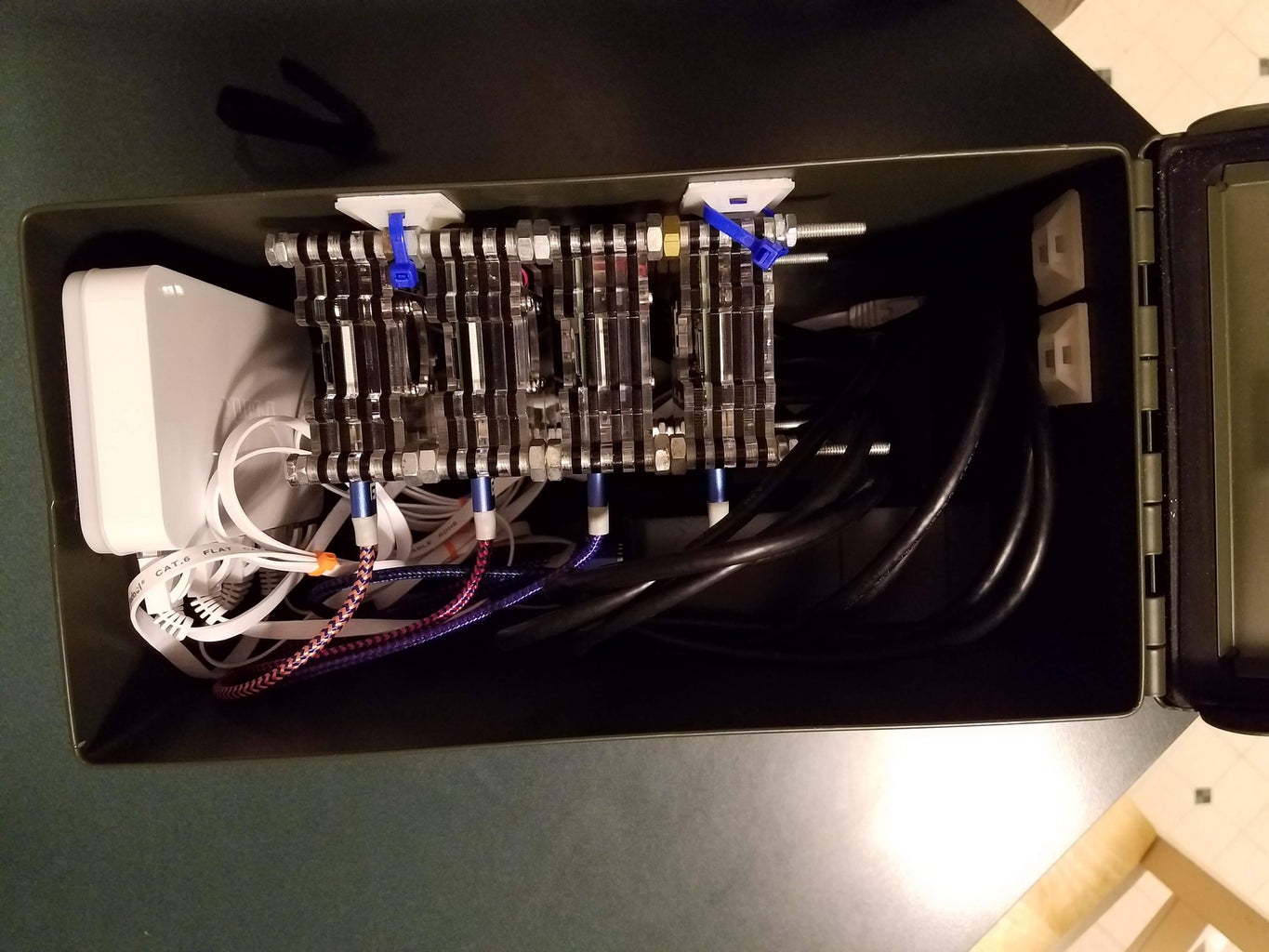
I used some Velcro to attach the power supply to the side of the unit. The switch and the plug cable go out the predrilled locations. Velcro again was used to put the Ethernet Switch to the front of the box, allowing space for access to the ports and power (all on same side). In the photo, you also see the power supply for the Ethernet switch and the USB cables for the Raspberry Pi units. I also used flat Ethernet cables, to help with winding things up.
Ethernet Switch : D-link 8-Port Unmanaged Gigabit Switch
4 qty: USB to microUSB adapters: 1 ft Braided short cables
5 qty: Cat 6 Ethernet Cable 3 ft White - Flat Internet Network Cable
Step 4: Raspberry Pi Stack Setup


This is a set of Raspberry Pi 3B units. I simply used a threaded dowel and nuts to stack the up the units. Each unit started with the same image, but was configured to a unique known static IP address for each unit.
I generally like the Smraza layered cases. It allows the stacking to work really well compared to a hard case.
So, too many photos but the stack was simply zip-tied to a zip tie mount. The Ethernet cable goes out the "bottom" of the stack, while the USB power goes out the side.
Make sure to have a configuration order for the IP addresses (.10, .11, .12, .13) and have them mapped to the USB output locations (USB1, 2, 3, 4) and wire the USB to each Pi. location. Make sure the mapping is known.
I suggest labeling the can, to show both the IP addresses as well as the USB location
Step 5: Naked Look


here are the photos of the naked system, without the can. Also, is the end result
What is missing are Logitech C920 cameras. These will all stream H.264 natively. Each Raspberry Pi is running from started a streaming source. I can't remember the package being executed, which is why Part 2 will handle the SW side.
The end result is
- Webcam -> USB 3.0 -> Bulkhead 1 (port 1) -> Pi -> (stream) -> Unmanaged Switch 1
- Webcam -> USB 3.0 -> Bulkhead 1 (port 2) ->Pi -> (stream) -/
- Webcam -> USB 3.0 -> Bulkhead 2 (port 1) ->Pi -> (stream) -/
- Webcam -> USB 3.0 -> Bulkhead 2 (port 2) ->Pi -> (stream) -/
- Unmanaged Switch 1-> Ethernet -> Bulkhead coupler
- Bulkhead coupler -> .Ethernet -> Unmanaged Switch 2 -> Ethernet -> laptop -> OBS Studio
OBS Studio will now allow you to manage the output of each of the cameras. You can create multiple scenes. Either 1 camera per scene, or create a quad image of all camaras in its own scene.
Stand by for the Software setup. Not difficult, but I still need to put that together.


