

Introduction: Recycle IP Power 9258 With a Raspberry Pi


A few years ago, I bought this device to control a couple of other devices and lights in my network shelf. It lasted a few years before it started to randomly power cycle every few minutes, and now it only beeps repeatedly when you turn it on. After succeeding with another instructable that I found here my first thought was to toss this junker into the trash. Then I thought "Why don't I just give this thing a heart transplant?"
I recently gained a lot of interest towards the Raspberry Pi and what it is capable of. I have certifications and years of experience for Windows operating systems but almost none for Linux...therefore you will need to look elsewhere for instructions on loading up Raspbian.
A special thanks to TheFreeElectron and rleddington for their inspirational Instructables that powered this one:
https://www.instructables.com/id/Simple-and-intuitive-web-interface-for-your-Raspbe/
https://www.instructables.com/id/Web-Controlled-8-Channel-Powerstrip/
You will need to follow their Instructables before you proceed any further with mine. This is my very first Instructable and I will be building this device as I write it. At this point, I do not know if it will work so you may first want to read all the way to the end to decide if you wish to follow along.
Step 1: Tools


Pliers - for quick connects you will need to use later on.
Wire stripper - because I couldn't use quick connects on the relay board >:(
RJ-45 crimper - you'll only need to crimp one end.
Wire cutter - I know that the stripper and crimper come with one as part of it, but I used a dedicated wire cutter to cut tougher wires and some plastic. You will see what I mean later on. The one you see in the picture is one I once used to help a previous landlord cut a fence that he was taking down. Even after a day doing that, it is still sharp and strong enough to cut thru all kinds of stuff.
Fingernail clipper - To hack away at some wiring strain reliefs that will get in the way later. You could use toenail clippers, but they are larger and may not be as precise.
Tweezers - helps connect jumper wires in small areas (my wife had a couple lying around)
Phillips head screwdriver (2 sizes) - a tiny size to remove the case screws. Medium to large size to remove the motherboard and to mount a USB port.
Basic knowledge on network configuration - Since there are so many ways to configure a network, I am unable to assist you with this portion.
Step 2: Install the Software

If you haven't already, you really need to read, and become familiar with the 2 instructables by TheFreeElectron and rleddington that I posted in my intro for the operating system install, setup and configuration of Apache, and connectivity to a relay board.
If you read TheFreeElectron's instructable, you will be able to setup the software and configure your Pi with no problem. I don't want to make you feel that you are getting the run around, but that instructable will lead you to an external site that lists things you need to do to your Pi to make that one work. Also, I'm not asking you to test it with LED lights as explained there. You should then read and follow rleddington's instructable to get your Pi working with a relay board. It is explained there on how to connect to a relay board with 8 relays, but its not really that difficult to divert off course from his steps a little to setup a board of 4 relays.
I used my knowledge on HTML to find the parts in the PHP and Java files posted on TheFreeElectron's instructable and modified them as needed to only make the first 4 GPIO connections available and controllable on the web interface. You will need to do the same, or else you will have 4 extra power buttons on your web interface that will do absolutely nothing.
Follow their steps with only the Pi and relay board to make sure they work. Doing this on an 8 GB SD card worked for me, although it took me a few tries to get it right due to my lack of Linux experience. Even though the Pi will have no monitor (a "headless Pi" is what I have heard), I have it booting to the GUI for any future maintenance needs that may pop up, and enabled SSH. Since it will always be turned on, I might be able to make a nice file server out of it in the future...should be interesting.
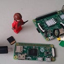
This picture shows my Pi model B with a nice clear case that I might have to remove.
One more thing: I know its very tempting, but DO NOT OVERCLOCK the processor. Being inside a metal case with no airflow is the absolute worst place for an overclocked processor to be. The software does not need that much processing power to work. In fact, if possible, you should underclock it. You should also install a heatsink on it. Regardless of what I do with them, I don't ever use any of my Raspbery Pi's without heatsinks.
Step 3: Shopping List


Raspberry Pi...duh. I am going to use model B because it has the an AV video jack and ethernet port. I will be using my years of experience playing Tetris to make this all fit together.
Leviton Cat 5e jack. The reason for this particuar brand is that it perfectly fits the network port opening on the IP Power case, though it won't snap in or be flush with the case. I will no longer have the luxury of link lights that were attached to the motherboard's ethernet jack, but sometimes life isn't fair. I'm about to put a Pi inside of this thing, so I see this as an acceptable loss. You can buy one of these from Home Depot, Lowes, Ace, or any similar store. I got this one from Home Depot and have seen it in orange, tan, white, blue, and black in case you want your jack to blend in with the color the case. A Cat 6 jack will work too. Avoid Cat 3 at all cost....
An RJ-45 end and about 6 inches of Cat 5 cable. You can use Cat 6 as well...doesn't matter because this will not require gigabit speed.
A relay board with 4 relays. I see these all over eBay; a few within the USA and most from China...its up to you. I got a bit ahead of myself on these steps and did some prewiring.
Female to femalejumper wire - I had to hunt around eBay to get one for a good price. I have seen the male to female and male to male jumper wires at RadioShack since they sell the Arduino, but those won't help you here...you specifically need female to female. It does not matter what colors you use.
This nice little panel mount USB port that I found on eBay. This will allow you to console connect to the Pi for any future maintenance that may come up. Like the relay board, these are mostly sold out of China, but I paid a little extra to ship from the USA.
Some type of double stick, foam pad to keep the Pi and relay board from sliding around. I used Command Strips since it was the first thing I found when I went out shopping for parts. You don't particularly need Command Strips, just anything padded. **Avoid double stick tape...it is not thick enough.**
Electrical tape to prevent some parts from short circuiting and ruining our efforts at creating a cool device.
Wiring quick connects. You can find these at most auto part stores. This prevents the need to splice so many wires and they actually hold stronger than if you were to twist some together and use electical tape.
AV Splitter. You can use either 1 female to 2 male or 1 male to 2 female. It won't matter because you will later be cutting one off to basically make a short AV extension cable. I required 2 of them to make this project work.
So...to shorten the list:
- Raspberry Pi
- Cat 5 jack
- RJ-45 end
- 4 port relay board
- Female to female jumper wire
- Panel mount USB port
- Command strips
- Electrical tape
- Quick Connects
- AV Splitter x2
Step 4: Rip Out the Guts....


Exactly what it sounds like. I did not take the time to find out why this device wasn't functioning, but I dont care either. This box contolled by a Raspberry Pi sounds like a better idea. There are 4 small screws on the bottom that hold the case together, 1 of them covered with a sticker that voids the warranty if removed (if there was even a warranty at all). Remove them and the case will easily slide apart. You will also need to remove the plastic nut holding the power reset fuse in place.
Once the case fully opened, most wires to the outer connections are attached to the board with quick disconnect plugs that I had to wrestle off with my pliers. There are 2 wires connected to the transformer on the motherboard that I had to cut since their quick disconnect plugs were covered with heat shrink.
The power reset switch should now be completely loose from the case and motherboard. You can set that aside for later if you still wish to use it. IMPORTANT NOTE: Keeping it is completely optional but I recommend you keep using it because of safety. I am placing a lot of effort into building this and I don't want it to burn up. I reconnected to the case so that I wouldn't lose it.
I temporarily removed 2 screws holding the IEC power input in place so that I could pull it out just enough to access one of the 3 screws holding down the motherboard. The motherboard can be removed and tossed into the trash if you don't want it. I did exactly that, but not before cannibalizing some useable circuits from it that I can use in the future.
Step 5: Clean It Up a Bit


If you disconnected anything from the outer connections (minus the fuse), you should reconnect them. This setup is already close to ready to be connected to a 4 relay board. One of the pictures above shows my Pi 2 with its case for size comparison. I don't plan to use my Pi 2 with this project since I use it for RetroPie. I am aiming to make this work with my Pi model B because it has an AV video jack. If I can't make it work, I will use a Pi model A+ that I have on order.
Also, if your Pi has a case, you may or may not need to remove it depending on the size and shape. If you find yourself needing to remove your case, the bottom of the IP Power case has a thin sheet of plastic to prevent short circuits. You can keep it there to do the same for your Pi.
Step 6: Tape the Shell


Just a side note: This whole step is completely optional, but you also have the option to just cover all the openings if you don't want or don't need external access ports.
No point at all in keeping the light holes open...cover 'em up.
This wasn't a network switch, it was a power switch so I don't quite know the purpose of the DB-9 "CONSOLE-RS232" port since this device was controlled over the network using its ethernet connection, however its port opening can be recycled so DON'T cover it.
The "OUTPUT" port looks like an S-Video cable on steroids...but I have no idea what it was for and it will still be useless later on so cover it.
I don't know the purpose of the "ON/OFF" buttons, nor did they do anything when this device was still working. One of the 2 holes can be recycled. Cover one, leave the other exposed.
The "NETWORK" port...cover it if you want, but I left it exposed. My Pi B is set to connect wirelessly with a tiny USB dongle, but I still wish to keep ethernet easily accessible.
Step 7: Network Connectivity

This step is completely optional. You could use a WiFi dongle instead for network connectivity, but be aware that it will be surrounded by grounded metal so its range will be significantly reduced. For that reason, I am going with a hard wired connection.
You will need to make an ethernet extension cable (no more than 6 inches needed). I grew up learning T-568B color code, but you can use whatever you wish...it just needs to be straight through. I connected one end to the Cat 5 jack then pulled the cable shielding completely off leaving only the 8 conductors, then crimped it to the RJ-45 end. Removing the shielding would normally not be a good idea, but I needed this cable to be as flexible as possible and to give myself that much more space for when I put this all together.
Step 8: Front Panel


If you decided to leave select ports uncovered as I explained in step 6, then read on. If not (or if you do not wish to add these convenient ports), you can skip this step.
I started with using an excessive amount of PVC rubber cement (used on water pipes) to mount my ethernet jack, but it was weak, messy, and ate away at the plastic a little bit. I had to use a knife to hack some of it away. I then used Gorilla Glue to reinforce it. I also did the same for a modified AV splitter. Be cautious not to get this on your skin because it could cause irritation and/or discoloration. Also try not to use as little as possible because Gorilla Glue foams up as it dries.
The USB can simply be mounted with screws.
Now you will need to use fingernail clippers to chip away at the strain relief of the USB and AV cables because they will get in the way when it's time to assemble.
Step 9: Electrical Setup


WARNING! This step is where you begin to hit the danger zone because doing any of this wrong could bring about disasterous results. Remember that these wires will have 120 volts AC running thru them. If something happens to you, then this is 100% on you therefore I am absolved of any legal actions. The only thing I will be responsible for is if something happens with my own device, not yours.
So assuming you have read and under stood rleddington's instructable, this step for the relay board is quite similar. The power input on the relay board should be connected to the output on the power fuse connected to the front of the case. Looking at the bottom half of the case with the power outlets facing away from you, they will be in reverse numbered order 4,3,2,1 so make sure to wire the relay board accordingly. You will only need to splice the end that connects to the relay board. The rest of the wires can be connected using quick connects.
After all the wiring connections are made, you can place a Command Strip on the bottom of the relay board to hold it in place. Still with the power outlets facing away from you, you will need ot stick the relay board to the bottom of the case to the far left with the wire connectors facing towards the center of the case.
Step 10: Pi Needs Power Too


I found these small usb chargers on sale at Walmart. They look like the one my wife uses to charge her iPhone. Even though I prefer Android, I don't want to destroy her charger so that is why I bought these. I bought 2 because I wasn't sure if i would be able to pop the case apart without breaking the circuits inside. I managed to get it right the first time though :)
Again, we are going to need as much space inside as possible, so that's why I removed the cover from the plug. I covered it with electrical tape to prevent short circuiting. I had to chisel down the plug end with my wire cutter to reduce its size as well. IMPORTANT: You will also need to put tape over the soldering on the plug end to prevent it from sending power to where it doesn't need to be.
I found this little power outlet at Home Depot. It looks like it was made to snap into certain things, but in this case, it is a good size for this project. Connect the white neutral wire to any of the white neutral wires on the case with a quick connect. Connect the black hot wire to the power fuse output (which will be shared with the power input on the relay board). This particular USB charger can be used at either polarity. Whatever one you use might be the same, but you want to make sure of that first. Connect the power outlet like I just explained and you won't have a problem.
Step 11: Pack It Up


Another danger zone here. Just make sure that metal from one part is not touching metal from another part and you will be ok. I also found myself needing to remove the case from my Pi.
Time to play Tetris. First place the relay board to the far left with the wires facing toward the center of the case like what you see in the first 2 pictures of this step, not the second 2. You may need to use tweezers to reconnect the jumper wires from the Pi to the relay board.
Connect the ethernet and USB from the front of the case to the Pi. You will need to keep tucking wires under the case as you slide it back together. No need to use excessive force. If you find yourself in that situation, you may need to pull it apart and readjust whatever is blocking it and try again.
This is literally the hardest part. It took me a few hours to get it and it is hard to get more pictures while doing it. If you skipped some steps above and avoided adding ports to the font panel, this should take seconds to reassemble. You could also make this puzzle much easier by using the A+ model with a WiFi or ethernet dongle on its one USB port, but as I said above, WiFi will have massive singal loss if you do that. Even 802.11n will have trouble connecting thru the grounded metal of the casing. As I said eariler, I am still sticking with model B because of its ethernet and AV video ports.
Step 12: The Ultimate Test.


After getting the case back together, I tested it right away and it worked.
For safety reasons, I plugged into a GFCI outlet. This way, if there is a short circuit, it would trip the breaker only on the one outlet instead of the circuit breaker which will knock out several outlets in the house. Most houses and apartments today have them in the bathroom. Mine has one in each of my 2 bathrooms, one in my basement that is daisy chained to all the other outlets, 2 in my kitchen, and one in my garage.
If overheating is of concern for you, then connect to your Pi using SSH, or using your newly installed front panel ports and run the following command:
/opt/vc/bin/vcgencmd measure_temp
Again, I am not a Linux expert. I found this in the forums on the Raspberry Pi site. The output will show the temperature in celcius format. Its starting to get cold out so my heater is heating my house to 68ºF...Google translates that to 20.5ºC. My Pi measured 44.3ºC right after booting, and 44.4ºC after running for about a half hour. I activated all the relays (which increases power consumption on the Pi), left it that way for over an hour and its temperature rose up to 48.7ºC. I waited another half hour (still with the relays activated) and the temperature was 48.2ºC. Needless to say, the temperature ain't moving around very much. It is 80ºC where the Pi begins to overheat.
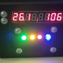
My powered items of choice were 4 guide lights I had lying around. These come in a 2 pack and I found them at Ace Hardware a few years ago. You can test your new device with any electronic, but I would suggest you start with the lowest power consuming item that you can possibly find before you move up. I don't know how much amperage it will take to burn out a relay, but I don't plan to try and find out. The relays on my board are stamped on them that they are rated up to 10 amps, but I will try to avoid going over 5 amps per outlet.
Now looking at the first picture in this step, I realize that the case has numbers 1-4 stamped and the web interface has 0-3 on my phone...the fact that I made this work with a Pi, I am celebrating too much to even care about that. Just rename the image files and that will easily solve that little confusion.
This project was a total success for me and I hope it will be for you too. Now to find out what to build next........


