

Introduction: Remote Control Ice-Block PCBs


Structures and sculptures made of ice and snow are cool, but we thought that they need something extra. Lights! They need lights. Humans delight at the effect of judiciously applied lighting. With this conclusion reached, it was decided, we will make remote control, battery powered blocks of ice.
The design had to be infinitely (hypothetically) expandable. We also wanted to control the lights from anywhere so we knew we needed radio communications. Then came the realization that we were about to put circuitry and hot LEDs very close to frozen water. Several ideas for keeping the two separate were considered. Ultimately, we came up with a simple and inexpensive solution to that problem.
A neat feature of the ice-block PCBs is that they could be placed inside of anything, not just big blocks of ice. Put them inside or behind Objects de art or inside some holiday decorations or maybe they could be night lights for your room.
The whole process of creation and fabrication can roughly be divided into 4 sections. Circuit design, PCB layout, programming, fabrication.
CAD software was used for the initial circuit design. With CAD software, components could be simply drawn into the circuit rather than creating or finding components for the PCB schematic capture. There is no avoiding the creation of new parts, but why do it until the design is finalized.
The circuit can be divided up into five sections.
- - The Li-Po battery charging section
- - The high-power voltage regulator section. In this case, set to roughly 5.4VDC
- - The 3.3VDC regulator for the nRF24. These devices can handle 5VDC signals but require 3.3volt power.
- - The uC and 2.54GHz radio
- - LED control section
The Ice Block PCBs use the ATtiny85 microcontroller which gives us just five IO pins to work with. The nRF24L01 radios typically require a minimum of five control lines. Five microcontroller pins and five radio pins doesn’t leave anything left over for doing fun things like controlling LEDs.
To get around this limitation, we used a technique pioneered by a fellow who calls himself Nerd Ralph. The circuit and code he developed allow an nRF24L01 to be controlled with just three IO lines.
Nerd Ralph's methods have been incorporated into the latest revisions of the RF24 Arduino library, making it even easier to use.
The remote-control is setup to only transmit and the LED control boards are set to receive only. In this way, we can get around some of the limitations of the nRF24L01 modules. For our purposes, we only need a single master nRF24 in the remote-control to send commands and any number of receiving nRF24s on the LED control boards.
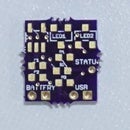
On the board is a MCP73831/2 lithium polymer battery charging IC. This IC gives the option of having the board charge the batteries from an appropriate USB power source rather that removing the batteries to be charge elsewhere. An undercharged battery will light up the red LED. When fully charged, the green LED the light up.
Step 1: Gather the Tools
- SMD Heat gun
- Soldering iron
- Solder wick
- heat gun or torch for heat shrink tubing
- scissors
- hobby knife
- hot glue gun & glue sticks
Step 2: Gather the Materials
Note that the quantities listed are for one LED unit and one remoter control unit only. You will need to adjust the parts quantities according to how many LED control units you intend to build.
Battery Management
- (1x) MCP73831/2 Li-Po Charger IC
- (1x) LED, Red, 3mm
- (1x) LED, Green, 3mm
- (2x) 470 ohm 1/8W 5% axial
- (1x) 2k ohm 1/8W 5% axial
5 Volt Supply
- (1x) MIC2288 Adjustable voltage chip
- (1x) 2.2uF cap, ceramic
- (1x) 22uF cap, ceramic
- (1x) 100k ohm 1/8W 1% axial
- (1x) 30k ohm, 1/8W 5% axial
- (1x) 10uH inductor
- (1x) Schottky Diode 1A 40V
3.3 Volt Supply
MOSFET Control
Microcontroller
Radio
- (1x) nRF24L01 2.4GHz Transceiver Module
- (1x) 1N4148 general purpose diode
- (1x) 22k ohm 1/8W 5% axial resistor
- (1x) 0.01uF capacitor, ceramic
External PCB parts
- (1x) 18650 protected cell or comparable 3.7v Li-Po battery pack
- (1x) 18650 battery holder
- (1x) USB Type-A Solder 4 Pin Male Connector
- (1x) LED, 1 watt 6000K
- (1x) Small heatsink
- (1x) 6 ohm 10W power resistor
- (1x) 3/16” heat shrink
- (1x) Arctic Silver Thermal Epoxy
- 20AWG stranded wire
Remote Control BOM
- (1x) Arduino UNO
- (1x) nRF24 2.4GHz radios
- (1x) nRF24 breadboard adapter
- (1x) 9-volt battery
- (1x) 9-volt battery clip
- (1x) 3.3-volt breadboard regulator
- (1x) 2.1mm x 5.5mm barrel plug
- (1x) Momentary button
- (1x) Breadboard, a 400 point or larger
- (1x) Jumper wire kit
Other Parts & Materials
Step 3: Create the PCB Files With EAGLE


We will go through the steps to create the ice-block PCB, but don’t worry, you won’t have to do any of this unless you want to. You can use the included files to skip to having boards made. However, should you decide to recreate the PCB, it will be a great learning experience. It is also an opportunity to change the design as you see fit.
Autodesk EAGLE PCB designer was used to create the ice-block boards. EAGLE is great software for many reasons, including the fact that for boards with two layers like this, it is free. Also, OSH PARK, the board-house that fabricated these PCBs is very easy to work with in regards to Eagle.
The board was laid out in roughly the same arrangement that was drawn out in CAD. The components of each section of the circuit where kept together. This is good practice and it assists with assembly and troubleshooting. The board could have been made far more compact than its final 1.25” x 1.55”. However, space was not an issue so minimizing its footprint was not a priority.
Step 3-1: Draw the ice-block circuit in the EAGLE schematic editor.
Step 3-2: Click the “generate/switch to board” icon pointed to by the big red arrow. This will auto-generate a board for you.
Step 3-3: Arrange the components on the board to resemble the arrangement in the schematic. BTW, look closely at the PCB where the ATtiny85 sits. You will see trace-breaks between each microcontroller pin and the rest of the board. This was done so that the connection between microcontroller pin and the rest of the PCB could be easily severed. The trace just needed to be scored with a hobby knife if the connection needed to be eliminated because of a mistake or a post-fabrication design change.
Step 3-4: Download the OSH PARK 2-layer board design rules file. Run the DRC “design rules check” by clicking the icon pointed to by the red arrow.
Step 4: Generate Gerber Files for the Board-House


Go to the OSH PARK CAM jobs page to download the 2-layer cam file. Note that you will download different files for different versions of Eagle.
Click the CAM processor icon.
Within the CAM processor window, click File -> Open -> Job… and then navigate to the cam file. Click on it to load it. Then click the “Process Job” button.
With the OSH PARK cam file loaded, the CAM Processor window will look like this. Unless you specify otherwise, Eagle will put the Gerber fills it generates in a default location. This can be less than ideal because it the save location may not be obvious and the Gerbers may be mixed with other files. Sorting the Gerbers from the other files at a location can be a real pain.
To save yourself a bit of effort, you can specify a save location for the Gerbers by clicking the “File” button pointed at by the red arrow. You will have to do this for each tab within the CAM window. Finally, to generate the Gerber files, click the “Process Job” button.
Step 5: Order the PCBs From a Board-House

You could go anywhere to get your boards made but we prefer OSH PARK. Their prices are hard to beat and the lead times, while not the fastest, are very reasonable. All you have to do is ZIP up the Gerber files, and upload them to the OSH PARK upload page.
PCBs from OSH Park.
Step 6: Populate the PCBs With Components


With the iron and SMD heat gun, solder components to the boards. Use solder wick to pick up any excess solder around the SMD components. If it looks like you removed all the solder with the wick, don’t worry, you didn’t. There is almost always enough solder left to do the job. Solder the nRF24 to the PCB last so that it doesn’t get in the way of installing the other components.
If the nRF24 pins don’t quite fit into the holes on the PCB, crush the pins into their mating holes with a pair of pliers.
Step 7: Solder the External Components to the PCBs


Apply short lengths of heat shrink tubing to the wires coming to and from the board.
Solder red and black wires to the appropriate terminals on the male USB plug. Here you can see the proper orientation for the positive and negative wires.
Bond a 1 watt LED to a heatsink with Arctic Silver thermal epoxy. Solder wires to the LED. Apply heat-shrink tubing to keep the wires together and to cover any exposed conductors.
Solder a 6ohm power resistor in series with the LED. Apply heat-shrink tubing to the junctions.
Solder wires to a 18650-battery holder. Dress them with heat shrink tubing.
If the battery holder grips the battery so tightly that is difficult to remove, get a length of ribbon or cut a strip off of a Mylar parts bag. Seat the battery on top of the strip as shown. Now you have a pull tab for easy battery removal.
Solder the completed accessories to the proper points on the PCBs. Pay attention to the polarity. If you didn’t already charge the 18650 batteries, then they can be charged now by plugging the USB A connector into a USB charger.
Step 8: Build a Remote-Control


The remote-control circuit is built around an Arduino UNO. Build the remote-control circuit onto a breadboard. You will have to use an adapter for the nRF24L01 module because its pin spacing is not compatible with the 0.100” hole spacing of breadboards.
Fasten the remote-control into a cardboard box with a few globs of hot glue. The nRF24 seen here is electrically identical to the types used for the ice-block PCBs except that it has an external antenna on it for extra range. Notice the on-off button jammed into a hole in the cover of the box.
Step 9: Program the Remote Control


Because the remote-control is controlled by an Arduino UNO, it is very straightforward to program.
Open the “library” manager by going to Sketch -> Include Library -> Manage Library.
Do a search for “RF24” to bring up and the RF24 by TMRh20 library. Select the latest version of the library and install it. Open the Arduino IDE and load the remote-control sketch. Set up the IDE for uploading to an UNO and hit the upload button. A quick indication of whether the upload and circuit are working properly, is that the LED on the breadboard will briefly flutter each time the button is pressed.
Step 10: Program the Ice-Block PCBs


The Arduino IDE does not come with the cores for programming the ATtiny85. A core is a file that tells the Arduino IDE how to handle a microcontroller or an Arduino board. Follow the LINK to the GitHub page with ATtiny cores. Instructions for installation will be found on the GitHub page.
This schematic shows the connections between an UNO and an ATTiny85 for In-System-Programming. Use jumper wires to connect an UNO to the ISP header on an Ice-Block PCB.
Shown here is where the PCB header pins go to on the UNO.
Load the “IceBlock PCB_Rx_1.ino” sketch. The ice-block PCBs are programmed with an Arduino UNO setup to function as an ISP (in-system programmer). Set the programmer type to “Arduino as ISP” in the drop-down menu.
Select the ATtiny85 with an 8MHz internal oscillator. This option won’t be available if you didn’t install the ATtiny 85 cores. Finally, upload the sketch.
Step 11: Make Blocks of Ice With a Pocket


Start with the Sterlite storage bin. Fill it with water. Then comes the slightly tricky part. The Sistema Klip-it container must be held down or else it will try to buoy itself out of the water. Snap the lid of the Sterilite container down onto the Sistema container. Now carefully put the container full of water into the freezer. Leave enough of the Sistema container above the waterline so that the lid can be snapped on and off. If you don’t, you will be chiseling ice out of the way to make room for the lids snaps.
After it freezes, you will have something that’s looks a lot like this.
Place a completed ice-block PCB and all its bits into the Sistema container.
Then snap the lid down on it. Pop the ice block out of the plastic bin. If it won’t release right away, let it sit out for a few minutes.
Step 12: Make the Ice-Block Light Up


The code for the remote-control is designed to just cycle through the different operating modes with each button press. You cannot cycle through modes by holding the button down, the debounce subroutine won’t allow it. The button must be pressed and then released to advance to the next mode. When in “mode 5”, another press of the button will just loop back to Mode 0.
The list of modes:
- Mode 0 - LED off
- Mode 1 - LED fade in and out fast
- Mode 2 - LED fade in and out slowly
- Mode 3 - LED slow blink
- Mode 4 - LED fast blink
- Mode 5 - LED on
This is a small display we built. It is kind of like a small remote-control igloo… or our collection of crystals pilfered from Superman’s fortress of solitude. The topmost ice-block on the pile doesn’t have a PCB in it. We just needed a cap for the igloo.
All the modes:


