

Introduction: Remote Controlled Robot Using Arduino


L293D is a dual H-bridge motor driver integrated circuit (IC). Motor drivers act as current amplifiers since they take a low-current control signal and provide a higher-current signal. This higher current signal is used to drive the motors.
L293D contains two inbuilt H-bridge driver circuits. In its common mode of operation, two DC motors can be driven simultaneously, both in forward and reverse direction. The motor operations of two motors can be controlled by input logic at pins 2 & 7 and 10 & 15. Input logic 00 or 11 will stop the corresponding motor. Logic 01 and 10 will rotate it in clockwise and anticlockwise directions, respectively.
Enable pins 1 and 9 (corresponding to the two motors) must be high for motors to start operating. When an enable input is high, the associated driver gets enabled. As a result, the outputs become active and work in phase with their inputs. Similarly, when the enable input is low, that driver is disabled, and their outputs are off and in the high-impedance state.
An infrared receiver, or IR receiver, is hardware that sends information from an infrared remote control to another device by receiving and decoding signals. In general, the receiver outputs a code to uniquely identify the infrared signal that it receives. This code is then used in order to convert signals from the remote control into a format that can be understood by the other device. It is the part of a device that receives infrared commands from a remote control. Because infrared is light, it requires line-of-sight visibility for the best possible operation, but can however still be reflected by items such as glass and walls. Poorly placed IR receivers can result in what is called "tunnel vision", where the operational range of a remote control is reduced because they are set so far back into the chassis of a device.
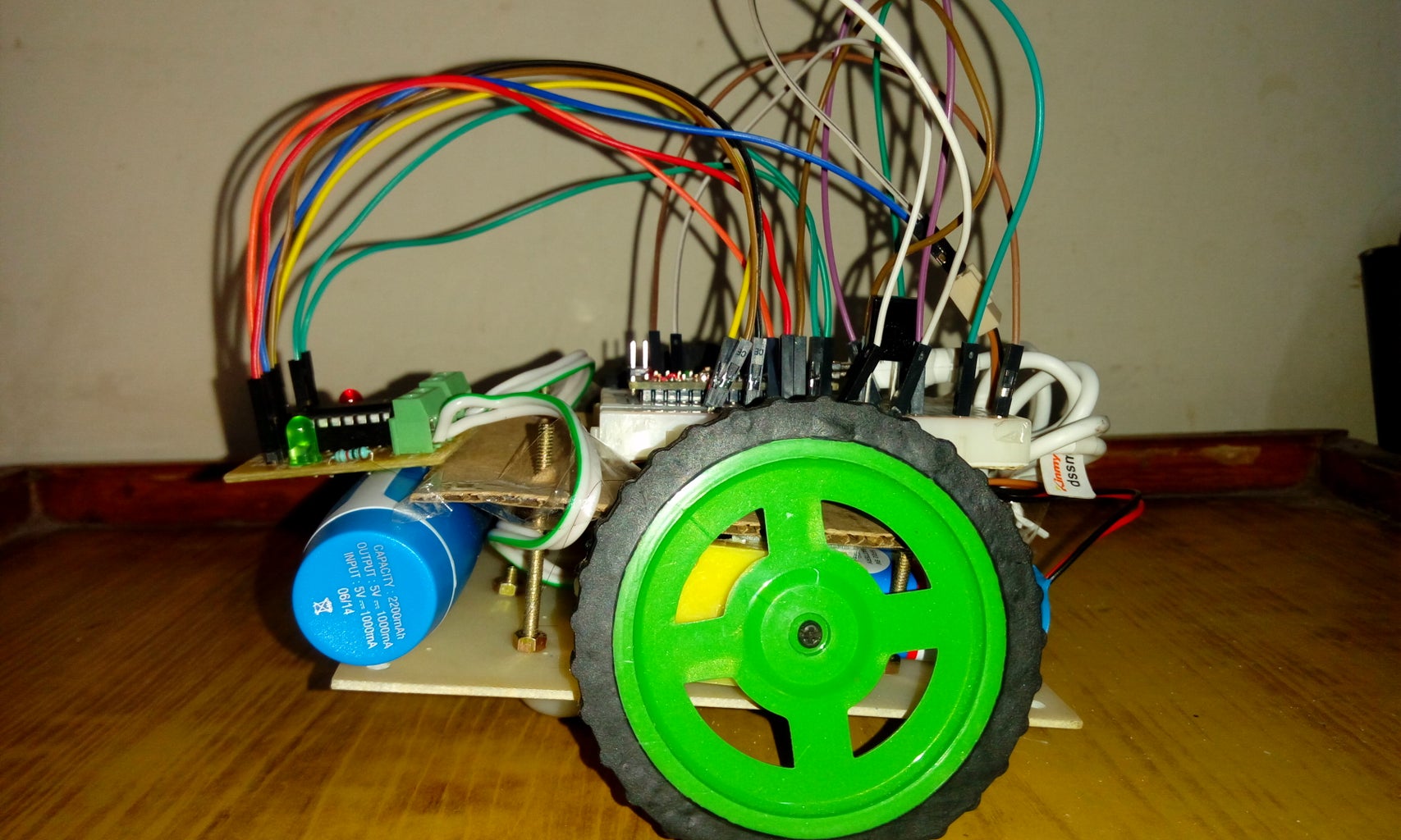
In this project, I have built a robot with the help of a chassis kit which is controlled by an IR remote.
Step 1: Componenets Required:
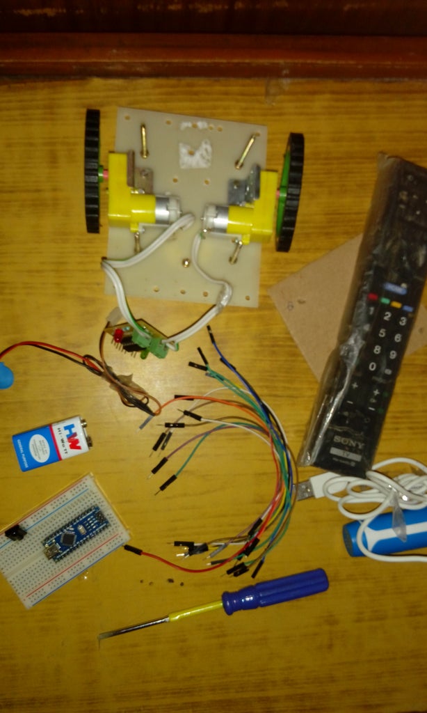
1. Arduino board (I've used Nano here)
2. L293D IC or L293D driver module. I used a module for this project.
3. Robot kit with chassis. You can purchase it from any online store or build one yourself!
4. IR receiver (TSOP 1737)
5. IR remote. You can use any remote lying in house.
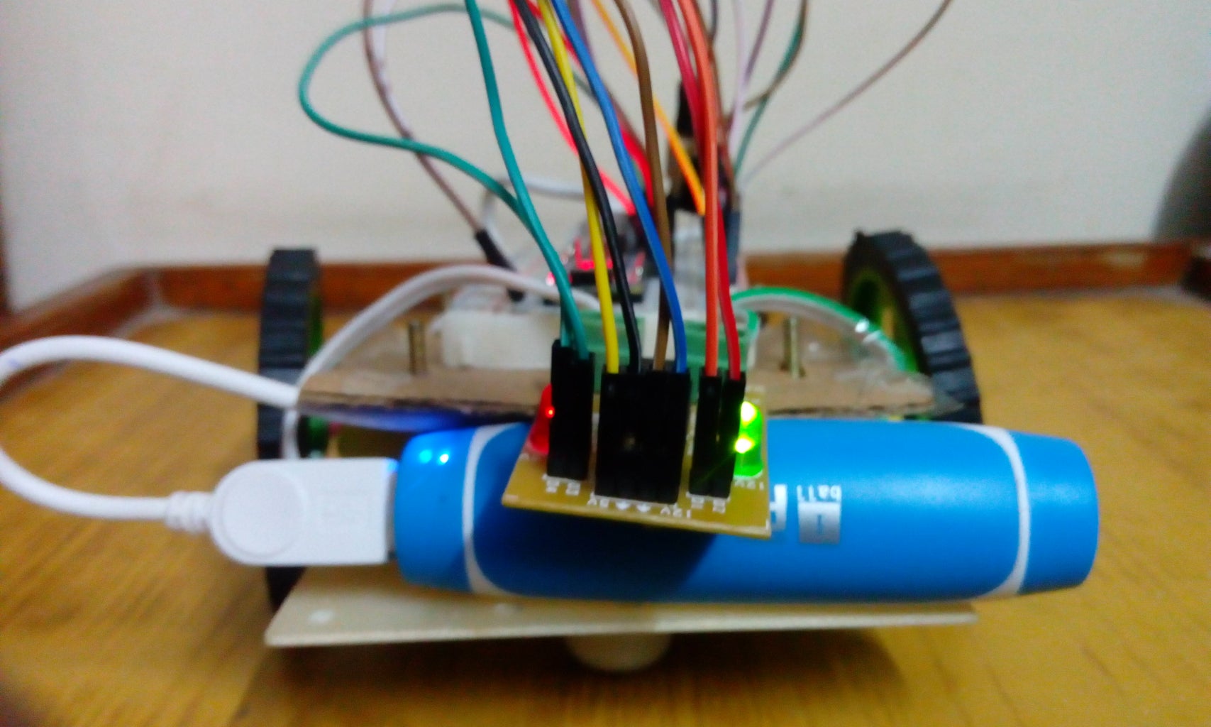
6. 5V battery for powering the Arduino board. I have used a power bank.
7. A 9V battery
Step 2: Assembling the Parts:

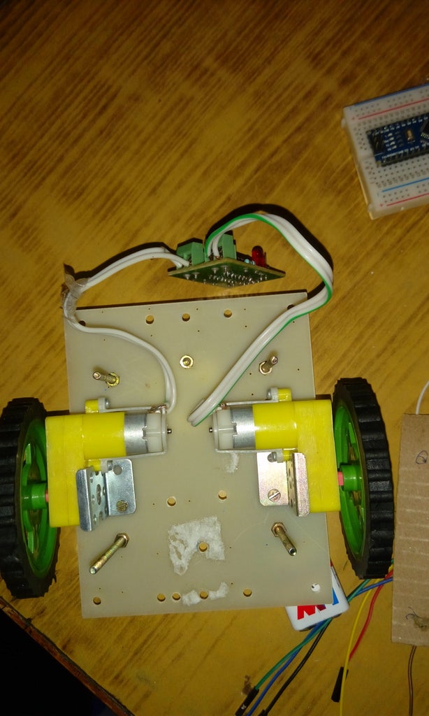

If you have a chassis kit then you can follow the guidelines given in the manuals.
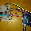
Step 3: Connections:


1. Pin 4 , 5, 12 and 13 from L293D Chip Connect to Ground
Pin 1, 9 and 16 from L293D Chip Connect to 5 Volts
2. Pin 8 from L293D connects to 9 Volts (Positive Lead of Battery Pack)
3. Pin 3 from L293D connects to Right Motor. Pin 6 from L293D to Right Motor. (Forward and Backward)
4. Pin 11 from L293D connects to Left Motor. Pin 14 from L293D to Left Motor.
(Forward and Backward)
5. Output pins on Arduino to control Right Motor :Pin 2 on the L293D to pin D8 on the Arduino board and Pin 7 from the L293D to pin D9 on the Arduino board.
6. Output pins on Arduino to control Right Motor :Pin 10 on the L293D to pin D11 on the Arduino board and Pin 15 from the L293D to pin D12 on the Arduino board.
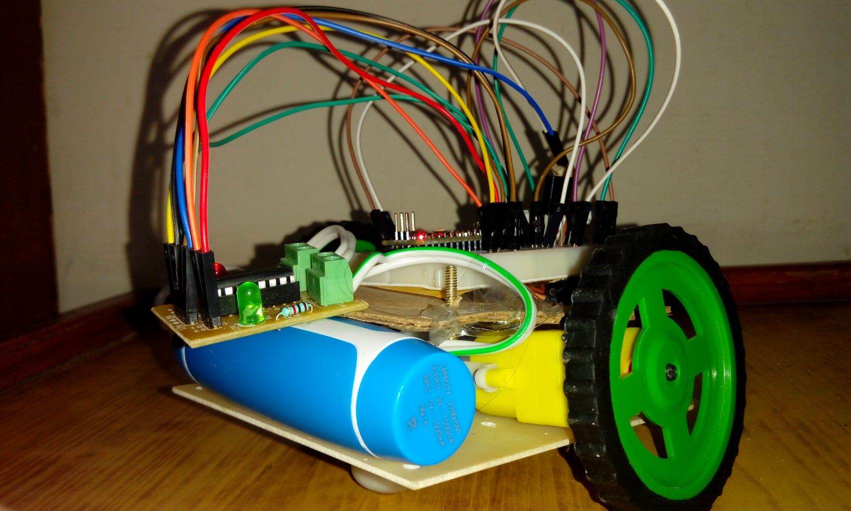
7. I have connected a power bank to power the Arduino board.
If you are using a L293D module like the one shown then connect the pins D1, D2 and D3, D4 of the module to the respective Arduino board outputs pins( The ones mentioned above). The motors are connected to the holders(M1, J3 and M2, J4). 5V pin is connected to the Arduino board 5V pin and 12V pin to the 9V battery.
Attachments

Step 4: Configuring IR Remote With Arduino

For controlling your robot with the remote, you first need to delete the 'RobotIRemote' and 'Robot_Control' libraries from the Arduino folder. Then install the IR remote libraries from here:
http://www.righto.com/2009/08/multi-protocol-infra...
Run the 'IRrecvDemo' code and find out the hex values for the keys of your remote. Convert these hex values into decimal using this link:
http://www.binaryhexconverter.com/hex-to-decimal-c...
For the IR receiver (TSOP 1737):
GND- Ground
Vss= 5V
Vout=D10
Step 5: Code:
The code is pretty simple. You can modify the example in the IR remote library.
int receiverpin=10;
#include //#include IRrecv irrecv(receiverpin);
decode_results results;
int leftMotorF=8; int leftMotorB=9;
int rightMotorF=11; int rightMotorB=12;
void setup()
{
// put your setup code here, to run once:
irrecv.enableIRIn();
pinMode(leftMotorF, OUTPUT); // initialize the pin as an output.
pinMode(rightMotorF, OUTPUT); // initialize the pin as an output.
pinMode(leftMotorB, OUTPUT); // initialize the pin as an output.
pinMode(rightMotorB, OUTPUT); // initialize the pin as an output.
}
void loop()
{
// put your main code here, to run repeatedly:
if(irrecv.decode(&results))
{
switch(results.value)
{
case 16:
digitalWrite(rightMotorF, HIGH);
digitalWrite(leftMotorF, HIGH);
digitalWrite(rightMotorB, LOW);
digitalWrite(leftMotorB, LOW);
break;
case 2064:
digitalWrite(rightMotorF, HIGH);
digitalWrite(leftMotorF, LOW);
digitalWrite(rightMotorB, LOW);
digitalWrite(leftMotorB, HIGH);
break;
case 1040:
digitalWrite(rightMotorF, LOW);
digitalWrite(leftMotorF, HIGH);
digitalWrite(rightMotorB, HIGH);
digitalWrite(leftMotorB, LOW);
break;
case 3088:
digitalWrite(rightMotorB, HIGH);
digitalWrite(leftMotorB, HIGH);
digitalWrite(rightMotorF, LOW);
digitalWrite(leftMotorF, LOW);
break;
default:
digitalWrite(rightMotorF, LOW);
digitalWrite(leftMotorF, LOW);
digitalWrite(rightMotorB, LOW);
digitalWrite(leftMotorB, LOW);
}
irrecv.resume();
}
}
Attachments
Step 6: Result!
You have your own remote controlled robot. You can even include an ultrasonic sensor for detecting obstacles. Here is the link for the ultrasonic distance sensor project:
https://www.instructables.com/id/Ultrasonic-Range-Finder-Using-Arduino/


