

Introduction: Remote Controlled Safe Box


This instructable was created in fulfillment of the project requirement of the Makecourse at the University of South Florida (www.makecourse.com). I will provide you with a brief introduction to my project, its control system block diagram, circuit board fritzing diagram and the final c++ code required to operate the device.
Step 1: Project Introduction
In the following steps, I will show you how to design a Remote Controlled Safe Box. My design for the safe box uses a remote control to send information to the arduino micro-controller through the IR sensor. The arduino then inputs this signal and uses it to control the servo motor and indicate to the user on an LCD screen and LEDs that the door is either locked or unlocked.
Step 2: Components..

The Safe Box project requires the use of the following components (the number in brackets indicate the quantity):
- Arduino Uno (1)
- 2x16 LCD display (1)
- Remote control (1)
- Green LED (1)
- Red LED (1)
- IR sensor (1)
- Servo motor (1)
- 9V Battery (1)
- 1k ohm Resistor (2)
- Breadboard (1)
- Connection Wires
Step 3: Assembling the Circuit..


Now, start by assembling the circuit as shown. If you stick to the exact same pins I use in the schematic provided, you would be able to run the code as provided. Pin# 3 and Pin#4 are used for the Green and the Red LEDs respectively. Please follow the same design for the LEDs (long leg connected towards the positive in series with a resistor, shorter leg to ground). Pin# 10 is used for the Servo motor. Pin#11 is connected to the IR sensor as shown. The LCD Display needs to be connected to the SDA, SCL, 5V and ground as indicated on the back of the LCD. The SDA and SCL pins are indicated on the bottom of the arduino (they are the last two pins as shown in the schematic).
Step 4: The Arduino Sketch..


After setting up the circuit, you need to connect the arduino to the computer through a serial connection. Once the arduino is connected, make sure its powered ( if it didnt power up, then there could be a short circuit somewhere). Then launch the ardunino c++ program and use the sketch provided in the images. The description of the each line is provided in the sketch.
As shown in the sketch, the servo motor will be the locking mechanism for our safe box controlled by either pressing number 1 or number 2 on the remote control. A rotation of 90 degrees between two fixed positions is sufficient to lock and unlock the door. Therefore, the arm length of the servo motor should be taken into consideration when designing the door lock.The LCD with tell the user whether the door is locked or unlocked.Further information will be provided in the next step.
Step 5: Designing a 3D Case


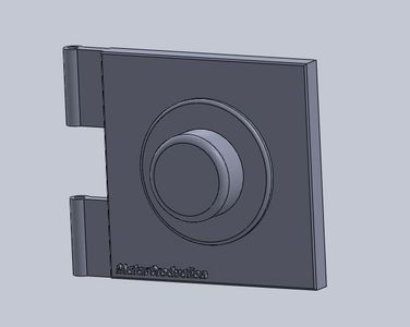

To design the safe box case, you first have to know the exact dimensions of the LCD screen, IR sensor, LEDs (diameter) and the servo motor in order to have a perfect design. I personally had different 3D designs, you can see in the image above one complete design for the safe box case, and a separated parts of another safe box design (this is due to the limited building platform of the 3D printer I own).
Step 6: Final Product!


Here is a final 3D printer design (sparyed with green and gold) of the safe box. Since the hinge pin was very delicate due to its size, I used a wire and placed it inside the hinge to hold the door and to act as a pivot. I hope you enjoyed my Instructable!
Thank you! :D


