Introduction: Reverse for a Battery Toy
Our 3-year old grandson loves his battery powered airplane modeled after Dusty in the Disney film, Planes. But, he frequently gets into a corner with it and must get off to drag the front end around physically so he can drive it again, I wanted to add a reverse gear.
The photo shows the location of the reversing switch. See the red arrow. The on/off switch is on the steering yoke and is operated by the thumb of the rider's right hand.
Tools--
> Drill and bits
> Screwdriver
> Knife
> Wire feed welder
> Crimping tool
> File
> Abrasive wheel or hacksaw
> Strong pliers
> File
> Dremel tool
Materials--
> Double throw, double pole switch
> Plastic covered wire, approximately #20 gauge
> Crimp end-to-end connectors
> 0.030 inch steel sheet
> Sheet metal screws
> 3/8 inch steel rod
> Plastic electrical tape
Step 1: Open the Toy
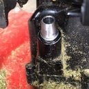
Remove the nut on the steering mechanism. (First photo.) Remove as many body screws as possible. I could not remove one screw under the gear train for the propulsion wheel, but I was able to pry the body halves apart far enough to reach inside and do what I needed to do. (Second photo.) I did need to slit stickers that bridged the two halves of the body. (Third photo.)
Step 2: Add a Reversing Switch
The original circuit is a simple series circuit involving a battery, an on/off switch, and a motor. In the photo the two wires I am holding go to the motor. I cut into the two wires coming from the battery and added #20 plastic covered wire to reach the area where the reversing switch would be placed. The other two wires going away from the switch go to the battery.
The polarity of the current flowing to the motor needs to be reversed to achieve a reversing gear. Notice that the wires I am holding connect to the terminals at one end of the double-pole, double-throw switch. Then they cross over one another in an "X" pattern and connect to the two terminals at the other end of the switch. The concern is that small fragments of wire will touch one of the other terminals. Insulate them with tape, or hot glue, or clip away any excess.
Step 3: Make a Metal Plate to Secure the Switch Orientation
Initially I tried simply tightening the nuts on the switch, but the switch still rotated in its 1/2 inch hole. A small child would simply push on the switch without realizing the switch had rotated. I needed to make a metal plate with a locking tab.
I cut a piece of sheet steel 0.030 inch thick and drilled a 1/2 inch hole in the center of it. I drilled two holes for mounting screws, one on either side of the larger hole. I placed the sheet steel piece on some thicker aluminum and built up what would become the tab that locks the switch from rotating. Then I filed the built up weld bead with a file to fit the slot in the switch. The aluminum backing kept the thin sheet steel from just melting and running away in blobs.
I bent the metal plate to fit the contours of the plastic body. I drilled for sheet metal mounting screws, and fastened the metal plate to the plastic body.
Step 4: Difficult Switch and an Extension
Extensions for toggle switches are available, but I could not find one locally. I decided to make my own. I drilled a hole down the center of a piece of 3/8 inch steel rod for a depth of the length of the toggle. Then I cut four lateral slots so I could close the end of the extension around the tapered section of the toggle switch. I also rounded and smoothed the end of the toggle extension.
The hole I drilled was not quite as large as the fattest part of the toggle. I went around the toggle a few times with a stone on a Dremel tool until the extension fit over the toggle.
I squeezed the sections between the slots together to hug the tapered toggle. This keeps the extension from coming off of the toggle. I thought I would need to weld the segments together with a tack weld on each slot, but it appears that will not be necessary. (See the second photo.)
Step 5: Assemble the Vehicle and Cover Rough Edges
I put black electrical tape over any rough edges. Another option would have been to place the steel plate below the plastic. I would have needed some machine screws, lock washers, and nuts; which I did not have at the time.
Now our grandson's electric riding toy has a reverse gear and the switch is easy enough to operate that he can manipulate it easily.


