

Introduction: Robo-Technician


Imagine for a second that you are one of the astronauts that lands on Mars. You have a million things to do, samples to take, experiments to run, data to collect, but once or twice a day you need to run around the habitation and/or research modules that you live and work in to inspect them. Its necessary, someone has to ensure that the thing is in good shape, that all of the thousands of pieces and parts are working and in place. But what if there was an automated helper to relieve you of some of those duties. What if there was a little robot that could move around inside the modules to make sure that everything was in place, working, and safe.
Robo-Technician to the rescue.
Essentially, this code controls the Robo-Technician as it follows a light colored path on the ground. It will follow this path until it it finds a junction in the path or a turn, which will prompt a photo to be taken for image processing to allow the Robo-Technician to make a decision on where to go next. The light bump and bump sensors work to protect the Robo-Technician from damage, and the bump sensors control when a diagnostic photo will be taken. All together, the Robo-Technician is designed to zoom around in the Mar's modules, freeing up the astronauts' time while doing the basic task of inspection, only calling for human input when it finds something wrong.
Again as a warning, this is a work in progress. The code, as it exists, works but it has it hiccups, especially since there are multiple, overlapping programs involved. Also, for this project to work in an actual Mars mission, a robot would need to be built for that specific purpose, so again I guess this is a "proof of concept" build.
There are a few things that you'll need to get this up and running. You'll need an expensive program, support packages for that program, and a little background in coding. As I am a student, and some of the ground-floor code has been provided (for the raspberry pi), I won't specifically talk about the set up. You can find all the links for that base code below. Let's get to the materials list.
Hardware
- Raspberry Pi (we used a version 3)
- iRobot ®
- some kind of holding device to keep the Raspberry Pi attached to the Robo-Technician
- Raspberry Pi camera (doesn't matter what kind, as long has good auto focus and image resolution)
- some kind of stand or holster to keep the camera facing forward on the Robo-Technician
- a material to use as a strip, white (or very light colored), that is held to the floor securely. It needs to be just slightly wider than the space between the front two cliff sensors.
- 4 signs with very large text (with the words IMAGE, RIGHT, BACK, and LEFT printed on them)
- Sheets of colored paper (at least three and preferably red, green, and blue)
Software
- Matlab (2018a and 2017b were both used and seem to make little difference)
- Raspberry Pi support package for Matlab
- Raspberry Pi code for connection to Matlab (link to the source code provided below)
- Image Processing Toolbox for Matlab (you pretty much can't do this project without the toolbox)
- OPTIONAL: Matlab Mobile installed on your phone, which I will explain later
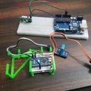
Step 1: Setting Up the Hardware
https://ef.engr.utk.edu/ef230-2018-08/projects/roo...
This is the link for the base code to ensure that the iRobot® can communicate with Matlab, along with a basic tutorial. As I said before, I won't cover this specific portion since the tutorial is very well laid out already. I will mention that once you have followed the steps on the link, you can use Matlab's "doc" command to look over the included information. Specifically:
doc roomba
And one more very important point.
When you download the files from the link above, PUT THEM IN THE FOLDER I DESCRIBED ABOVE, since Matlab requires user generated files to be in the current working folder.
With that out of the way, let's move onto the code.
Step 2: Finding All Those Sensors


Take a second and give the iRobot® an inspection. Its good to know where these are so you have an idea of the inputs the Robo-Technician is recieving, and you'll be able to figure out why the thing is spinning in circles instead of following the path you'll setup (this might or might not have happened). You'll obviously see the big physical bump sensor on the front. The cliff sensors are a bit more difficult to see, you'll need to flip it over and look for the four, clear plastic windows near the front edge. The light bump sensors are even more hidden, but for now it'll be enough to say the live in the shiny black band the runs around the front of the iRobot®, which is on the front of the physical bump sensor bar.
There are wheel drop sensors, but these are unused in this project, so we'll move onto testing the sensors.
Step 3: Testing to Set Parameters

Before we can send the Robo-Technician off to do it's job, we need to figure out its specific quirks and sensor ranges. Since each iRobot® is a little different and change over the life of the robot, we need to figure out how the sensors read over the areas it will be operating in. The easiest way to do this is to set up you light colored path (I used strips of white printer paper but anything light colored will do) on the surface that the Robo-Technician will operate.
Start up Matlab and open a new script. Save the script IN THE SAME FOLDER I DESCRIBED EARLIER and name it whatever you want (try to keep it short though, since the name of this file will be the function name). Turn on the robot and use the roomba variable setup from the tutorial, typing the commands into the command window.
Make sure the Raspberry Pi is plugged into the iRobot® and you're computer is connected to the same internet connection. You'll spend less time pulling out your hair trying to figure out why Matlab won't connect.
r = roomba(number you set up)<br>
The variable " r " in this circumstance is not necessary, you can call it whatever you want, but it does make life easier to use a single letter variable.
Once the path is setup, and the roomba has been successfully connected, place the future Robo-Technician where one or two of the cliff sensors are over top of the path. Obviously that means the the other two or three are over top of the surface you chose.
Now start up the test sensors with the command:
r.testSensors<br>
Keep in mind that the " r. " is the variable you defined earlier, so if it's not ' r ' change the ' r.' to whatever you decided on. This will bring up the test sensor screen with a ton of info.
For this project focus on the lightBumpers, bumpers, and cliff sections. Move the Robo-Technician around making sure to watch how the sensors change over different surfaces, or how close an object needs to be for the ligthBumper values to change, etc. Keep these numbers in mind (or write them down) because you'll need them to set you're parameters in a second.
Step 4: Starting the Code
First off you will be constructing a function. I called it "path" but again, the name is not necessary, but I'll be referring to it as "path" from now on.
The top portion of the code is setting up some user input options. It builds some lists that will be used in the in listdlg and then brings up a list dialogue box. This allows the user to select which path color they wish to follow, which comes into play later.
list = {'Red','Blue','Green'}


problist = {'Casualty, Save Image','Component Out of Place,Save Image','Expected, Continue'}

pathcolor = listdlg('PromptString','Select a Path Color',...
    'SelectionMode','single','ListString',list)


prob = 0;
driv = [];
The "prob" and "driv" variables need to be declared here as they will be used inside of the function's main while loop, but again, if you want to rename any of these variables or change the list selections, it's fine as long as you're consistent in the rest of the code.
Step 5: Top of the While Loop : Physical Bump Sensors
The top of the while loop contains the physical bump sensor logic. Basically, when the Robo-Technician runs into something it stops (or for the front bump sensor it backs up 0.1 meter), then positions itself to take a picture. Lets cover the velocity and position control portion first.
If you tested all the sensors on the Robo-Technician in the previous steps, you'll know that the bump sensors have a logic value (0 or 1) with zero representing the normal, not-pressed position of the sensor. Keep that in mind for the code.
while true %main while loop<br>        %receive bumper info
        S = r.getBumpers

	if S.left ~= 0
            r.stop
        elseif S.right ~= 0
            r.stop
        elseif S.front ~= 0
            r.stop
        end
This is the basic " if it hits something, stop" part. If the sensors do detect a collision, then it moves onto the next portion of the code, which readjusts the position of the Robo-Technician to get a photo.
if S.left ~= 0 %if loop takes bumper info and aligns camera for photo<br>            r.turnAngle(5)
            pause(0.5)
            img = r.getImage %takes photo and displays
            image(img)
            %dialog box
            prob = listdlg('PromptString','Found an Unexpected Obstacle, Please Identify'...
                ,'SelectionMode','single','ListString',problist)
        elseif S.right ~=0
            r.turnAngle(-5)
            pause(0.5)
            img = r.getImage
            image(img)
            prob = listdlg('PromptString','Found an Unexpected Obstacle, Please Identify'...
                ,'SelectionMode','single','ListString',problist)

        elseif S.front ~= 0
            r.moveDistance(-0.1)
            pause(0.5)
            img = r.getImage
            image(img)
            prob = listdlg('PromptString','Found an Unexpected Obstacle, Please Identify'...
                ,'SelectionMode','single','ListString',problist)
        end
Basically, once the image is taken another dialogue box will appear with three options. The first two options saves the photo to a specified folder, which I'll cover later, while the third option simply closes the dialogue box and continues through the loop. If you can't remember the options, take a look at the previous step.
Now I inserted a code section in between the bump sensor portion and the photo saving portion. This takes lightBumper values and sets the drive velocity to 0.025 meters/second (very slow), which is not actually necessary but it does cut down on the Robo-Technician banging into things and eventually wearing out the physical bump sensors.
L = r.getLightBumpers<br>        if L.left > 100 || L.leftFront >100 || L.rightFront  >100 || L.right  >100
            driv = 0.025
            r.setDriveVelocity(0.025)
        else driv = 0.1
        end
This would be the part where the values that you observed (and hopefully wrote down) earlier come into play.
The "L.(side and direction of sensor) > 100" was based on the values I observed, so if your observations are different, change these numbers. The idea is that if the Robo-Technician senses something a few centimeters in front of it, it will slow down, any more than that is unnecessary.
The next portion is where photos are saved for later.
%if first or second option was selected in prob dialog, saves image<br>        if prob == 1 %if loop builds file info for photo, writes with timestamp
                t = clock;
                basename = sprintf('\\img_%d_%d_%d_%d_%d.png' , t(1),t(2),t(3),t(4),t(5));
                folder = 'E:\UTK\Classes\fall 18\ef230\irobot\images';
                fullFileName = fullfile(folder, basename);
                imwrite(img,fullFileName)
                close Figure 1
                pause(2)
        elseif prob == 2
                t = clock;
                basename = sprintf('\\img_%d_%d_%d_%d_%d.png' , t(1),t(2),t(3),t(4),t(5));
                folder = 'E:\UTK\Classes\fall 18\ef230\irobot\images';
                fullFileName = fullfile(folder, basename);
                imwrite(img,fullFileName)
                close Figure 1
                pause(2)
        end
All of the filenames and locations where the photos are saved are optional. I chose a folder that is nested inside the roomba folder I created in the introduction step, but it can be anywhere you choose. Also, the photos are saved with the timestamp, but that is not especially necessary (though it would be hypothetically useful for a Mars mission).
With the physical bump sensors covered, we can move onto the cliff sensors and path following.
Step 6: Following the Path
The code for the cliff sensors is set up to compare values of the two front and two side sensor values. You'll need to change these values (probably) based on your observed values. You'll also probably need to edit these values after a few test runs and change them based on the ambient light, time of day (depending on how well lit the test area is) or when the sensor windows are dirty.
Before we get to the cliff sensor code however, there is a short code segment I inserted to flush some of the unnecessary data from Matlab. This part is not needed, but I used it to cut down on the storage required to run the program.
clear img
        clear t
        clear basename
        clear fullFileName
        clear folder
The next code segment is the meat of the project. It allows the Robo-Technician to follow the light colored path that has been placed on the floor. In a nutshell, it tries to steer itself so the front two cliff sensors are above the threshold, based on your observed values, and allows the program to begin the image processing steps a little later on.
C = r.getCliffSensors
        %if loop follows a color band(white)
        if C.leftFront > 2000 && C.rightFront >2000 %straight path guidance
            r.setDriveVelocity(driv)
        elseif C.leftFront < 2000 && C.rightFront >2000 %turns right if robot goes too far left
            r.turnAngle(-2.5)
        elseif C.leftFront >2000 && C.rightFront<2000%turns left if robot goes too far right
            r.turnAngle(2.5)
        elseif C.leftFront <2000 && C.rightFront <2000 %stops if the end of path is reached
            r.setDriveVelocity(0.0)
            %takes image, defines shape
            if L.left > 100 || L.leftFront >100 || L.rightFront  >100 || L.right  >100
            img = r.getImage
            end
            %checks to see if there is a bend in path
            if C.left >2800 && C.right <2800
                r.turnAngle(2.5)
            elseif C.left <2800 && C.right >2800
                r.turnAngle(-2.5)
            end
            %place holder for path image recognition
            disp('GETTING IMAGE')
        end
    end
end
Keep in mind that the variable names I chose are optional, but again I think it makes life easier to use single letter variables when possible.
To explain the middle section of the code, when the two front sensors run off the edge of the path (when it comes to an intersection or when it reaches the end of the path) it looks to see if there is something in front of it. You'll need to place an object on the ground at the end of the path or at any intersections for this to work.
Once the photo is taken it uses image recognition to figure out what to do. There is a place holder in this section of code as well:
%place holder for path image recognition
disp('GETTING IMAGE')
I used this for the moment because I wanted to talk specifically about the text and color processing that occurs, which is in the next step.
Step 7: Image Processing
There are two parts to the image processing. First is the color recognition, which calculates the color intensity in the picture to decide whether or not to continue on to text recognition. The color calculations are based on what choice was made in that very first dialogue box at the beginning (I used red, blue, green but you can choose whatever colors you want, as long as the mean values for color intensity can be recognized by the Raspberry Pi camera).
img = r.getImage
            img = imcrop(img,[0 30 512 354])
            imgb =imcrop(img,[0 30 512 354])
            imgt = imcrop(img,[0 30 512 354])
            red = mean(mean(imgb(:,:,1)));
            g = mean(mean(imgb(:,:,2)));
            b = mean(mean(imgb(:,:,3)));
This is the intensity check. This will be used in the next segment to decide what it wants to do.
if red > g && red >b
                if pathcolor == 1
                    imgc = imcrop(img,[0 30 512 354])
                    R = ocr(img)
                    if R.Words{1} == IMAGE || R.Words{2} == IMAGE || R.Words{3} ==IMAGE
                         t = clock;
                            basename = sprintf('\\img_%d_%d_%d_%d_%d.png' , t(1),t(2),t(3),t(4),t(5));
                            folder = 'E:\UTK\Classes\fall 18\ef230\irobot\images';
                            fullFileName = fullfile(folder, basename);
                            imwrite(img,fullFileName)
                            pause(2)
                    elseif R.Words{1} == RIGHT || R.Words{2} == RIGHT || R.Words{3} ==RIGHT
                        r.turnAngle(-75)
                    elseif R.Words{1} == LEFT || R.Words{2} == LEFT || R.Words{3} == LEFT
                        r.turnAngle(75)
                    elseif R.Words{1} == BACK || R.Words{2} == BACK || R.Words{3} ==BACK
                        r.turnAngle(110)
                    end
                else r.turnAngle(110)
                end
            end
This segment decides if the color that was selected in the first dialogue box matches the color the camera is seeing. If it does it runs text recognition. It looks to see which word (IMAGE, BACK, RIGHT or LEFT) appears and then either turns (for right and left), spins around (for back) or takes a picture and saves it in the same manner as earlier.
I've only provided a single section of the code for the different colors.
To allow the code to recognize blue and green, simply copy the code and change the logic check at the top of the segment and set the " pathcolor == (number) " to correspond to the color selections from the top dialogue box (for the code as it is displayed, blue would be 2 and green would be 3).
Step 8: The Finished Product

Now the Robo-Technician should zoom around the Mars mission modules and report back to the astronauts when anything is out of place.
Remember, all of the cliff sensor and lightBumper values need to be changed to what your observed values are. Also, from experience I've found it better to test this project on a dark colored floor and its even better if that floor is non-reflective. This gets the contrast to increase between the path and the floor which makes it more likely that the Robo-Technician will follow it correctly.
Hope you enjoyed setting up a little helper for the Mars mission, and have fun building.


