

Introduction: Robot Servo With Idle Horn


The purpose of this instructable is to provide a "shell" that can be used to convert a common servo motor to a robot servo with an idle horn. The idle horn (opposite the main drive horn) spins and allows easy connection of a C joint.
When I built Santa's Shop, I had 32 robot servo motors (with an idle horn opposite the main horn) in the animatronic figures and they had to operate 4 hours per day for about 35 days. Two of them failed during the season, while there were no failures in my creations using cheapo servos.
For this project, I used my "shell" on three servo motors and built an arm.
Step 1:

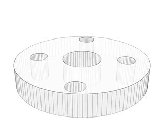
I designed the parts using Fusion 360 and included the design files here. I used Hitec HS-311 servo motors, but the idea is that you can choose your own standard size servo motor and build robot joints to your own specifications.
(3) Hitec HS-311
Arduino Uno
12 volt dc power supply
6 volt, 2 amp dc power supply (I used 4AA batteries)
3d printed parts, wood, screws, solder, wire
Attachments


Step 2:

Attach the hand to a bracket--I melted them together using a soldering iron.
Step 3:


Insert a servo motor into the main bracket.
Step 4:


Using 2-56 machine screws and nuts, I slide the motor toward the top (end with no screw holes) of the bracket and secure the motor. There has to be some play in the bracket to allow the motor and its cable to slide in.
Step 5:

Mount a servo horn to the C bracket.
Step 6:

Mount another servo horn to the side of the C bracket.
Step 7:


Slide the C bracket over the motor. The idle horn on the back side should be in place and it will be secured to the C bracket using M3 (8mm) screws. Secure the horn to the servo motor with the horn's screw.
Step 8:


Attach the shoulder servo motor to the servo horn on the C bracket. You can tighten the servo screw at this time.
Step 9:

Attach a servo bracket assembly to the hand assembly.
Step 10:


Attach an end bracket to the hand assembly. Note that there are two end brackets with different screw configurations--choose the one that fits (parallel or perpendicular)--perpendicular in this case.
Step 11:


Attach the hand assembly to the "shoulder upper arm" assembly.
Step 12:


The shoulder can be attached to 1" x 2" wood using 2-56 machine screws.
Step 13:


Printed end supports fasten to the bottom of the 12" long 1 x 2's.
Step 14:

Secure the arm assembly to a base so that it won't fall down.
Step 15:


Wire according to this schematic and secure the servo motor wires with zip ties.
Step 16:

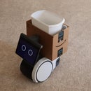
The assembly should look like this. A sketch to "wave" and "point to the chest" is included here.
Attachments

Step 17:

Servo motors with higher torque or other joint configurations should be possible. When refined and tested more, I would like to create molded plastic parts so that people without 3d printers could use these joints.

Participated in the
Robotics Contest 2017

Participated in the
Design Now: In Motion Contest

Participated in the
Microcontroller Contest 2017


