

Introduction: STEM - Voice and Image Control


Over the past few years it has become increasingly easier to make something with voice or image recognition. Both are being used more and more frequently nowadays. And these are popular topics in DIY projects. Most of the time created with the software/API from one of the following companies:
- Google Voice.
- Amazon Alexa.
- Microsoft Cognitive Services.
There are even some DIY kits, like the Google AIY Voice Kit to support hobbyists. Most of these products use a Raspberry Pi or a similar board. Unfortunately, this is not suitable for those who don't know how to handle a programming language, such as Python.
This instructable is about voice recognition and image OCR, without any knowledge of a programming language. However, logical thinking remains a requirement. Hereby the Makeblock Neuron product is used, combined with a flow based programming environment.
This Neuron product started as a Kickstarter project in 2017. It's an Electronic Building Block Platform using all types of electronic 'blocks' which can be connected by magnetic connectors. And is basically meant as a STEM (Science, Technology, Engineering, and Mathematics) product. This product therefore focuses on logical thinking and (learn) to program.
There are about 30 different types of Neuron blocks. Such as different types of transmitters and receivers, buttons, LEDs, sensors and motors. Most blocks only communicate with each other. But one of the blocks, the WiFi block, can be connected to the internet. This makes it possible to access internet applications such as the Microsoft Cognitive Services.
The first steps of this Instructable start with a brief introduction about the Neuron product and how to program them. This includes flow-based programming and some of the available electronic components.
This is followed by some examples with Vision and Voice recognition. And finally a small turtle robot. Which can be remotely controlled by means of a joystick. It is possible to use voice recognition with this robot. However, the response times of the voice control must be taken into account.
In addition there is some additional technical information. These steps provide background information and provide insight into the Neuron product.
GosseAdema
Step 1: Neuron Explorer Kit


Neuron blocks are like electronic bricks, and the color of each Neuron shows it's main function. Energy and communications blocks are green; Input blocks are Yellow; Control blocks are orange; And output blocks are blue. Each Neuron has it's own dedicated function, and they start to communicate with each other when they are connected to each other.
The product started as a Kickstarter project in April 2017. And this instructable uses the Explorer Kit. This Kit contains the folowing parts:
- WiFi (Neuron)
- Power (Neuron)
- Microphone & Speaker (USB)
- Led Panel 8x8 RGB (Neuron)
- Joystick (Neuron)
- Knob (Neuron)
- Led Strip Driver (Neuron)
- Led Strip 50cm (15 LEDs)
- Dual DC Motor Driver (Neuron)
- DC Motor (2x)
- Motor Bracket (2x)
- Wheels (2x)
- Mini Wheel
- Dual Servo Motor Driver (Neuron)
- Servo Motor (2x)
- Voice Recognition (Neuron)
- Utrasonic Sensor (Neuron)
- Wireless Transmitter (Neuron)
- Wireless Receiver (Neuron)
- Camera (USB)
- Laser Pointer
- Neuron Board (4x)
- Magnet Wire 10 cm (2x)
- Magnet Wire 20 cm (2x)
- Micro USB Cable 20 cm (2x)
- Micro USB Cable 100 cm (2x)
This kit contains all electronic parts for all kind of STEM projects. It's primary focus point seems to be making small robots. But the camera and voice recognition gives it way more possibilities than just robots.
Each Neuron contains a magnet. And can be placed on metal objects or on the supplied Neuron boards.
The only part that's "missing" in this Explorer Kit is a line follower sensor. This is a part of the "All in One" Kit. This sensor would be a more logical choice, instead of the LED strip or LED matrix.
Step 2: Neuron Blocks


Several Neuron packages were sold through a Kickstarter campaign. And at this moment the first packages are available for regular sales.
There are about 30 different blocks, which can be connected to each other with magnetic connectors. This creates a line of blocks. Which communicate with each other through the App (Android, iOS).
There is a rechargable power block which powers all connected blocks. And all communication blocks have a micro USB connector, which can be used to power the blocks. A chain normally starts with a communication block. And if this isn't powered by USB, the next block should be a power block.
The energy an communication blocks have a green color, and there are 5 of them:
- Power.
- Wireless Receiver.
- Wireless Transmitter.
- WiFi.
- BlueTooth.
The App and Scratch program require a WiFi or BlueTooth connection. The 2 wireless blocks can be used for remote controlled projects with a short distance.
The Explorer Kit contains three orange control blocks:
- Knob.
- Joystick.
- Voice Recognition.
And two yellow sensors:
- Camera
- Ultrasonic sensor
Control and sensors blocks provide input for your program. The knob gives a value between 0 and 100, and can be used as a dimmer or to control the speed of a motor. The joystick gives two values beteen -100 and 100, one value for each direction.
The ultrasonic sensor measures the distance in centimeters. The output value is between 0 and 400.
The five blue output blocks in this kit are:
- LED strip driver + Led strip.
- LED panel.
- DC Motor Driver
- Servo Motor Driver
- Microphone and Speaker
The output blocks are very various. This allows for many different types of projects. Like a LED lamp, a moving robot and/or a sound recorder.
All Neuron blocks are listed on the Kickstarter page.
Step 3: Programming the Neuron


There are several ways to use the Neuron blocks.
- Offline.
- Online with an App.
- Online with mBlock Scratch.
Offline offers an easy way to introduce the different parts. This requires no programming. Online programming can be done with an App (Android/iOS) or a computer program (mBlock 4.0). The WiFi block has the capability of saving a program. This program stays running until it's stopped by the App.
The App is easier to use than the mBlock 4.0 software. And not all Neuron blocks are currently present in the mBlock software.
There are some cards with sample projects in the Neuron box. These can be put together with the help of the App, and show the basic principles of the various blocks.
Step 4: Offline Mode


This mode is mainly meant to get acquainted to the product, and it doesn't require any programming.
Each sensor of output block is capable of providing output to the blocks attached to the right. And each display block can receive input signals from the left; Gives it's output; And passes the input signal to additional blocks connected to the right.
By this an offline chain always contains multiple blocks in a fixed order: A green Power block; A yellow or orange (input or control) block; And one or more blue output blocks. And this offline mode only works from left to right (with readable letters).
An input or control block controls all following output blocks. And the output depends on the type of input block. For example: The knob acts like a dimmer when connected to a LED matrix. And the joystick shows the direction on the LED matrix. Signals from multiple input blocks can't be combined in the offline mode. Only the signal of the last block is passed to the output blocks.
Combining input and/or control blocks requires the online (programming) mode.
Step 5: Flow Based Programming

When Neuron blocks are connected to an tablet (iPad) they automatically become active in Online mode. Now all connected blocks can be used to interact with each other. While the program environment adds logic and math operations.
The documentation about programming the Neuron blocks is available at the Makeblock website. There is also a forum which gives much information. Because this product is rather new, there are regular updates and additions to the documentation on the Makeblock website.
The Neuron App uses flow based programming. In addition to the Neuron blocks which give output values or require input values, there are all kind of different programming nodes. These are divided in several areas and have been placed on different tabs inside the App. By default, there are 4 tabs:
- Basic
- Controls
- Time
- Advanced
These programming nodes can be used without Neuron blocks.
The Makeblock online documentation shows the features of the App interface.
Logic and Math
These are basic functions. And have one or two inputs and one output value. There are several simple calculations and comparisons.
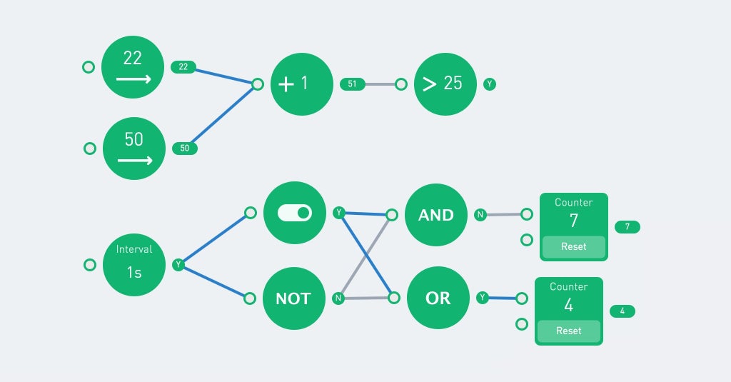
The toggle function switches it's state each time it receives a 'Y'.
Numbers
There are two number nodes, one "basic" and one "controls" version (they are on different tabs). The controls version is a fixed number, while the basic number has an 'on' and 'off' state. The following example shows the difference. The interval switches on ('Y') and off ('N') each second. The output of the green number is 5 when the input is 'Y', else the value is 0.
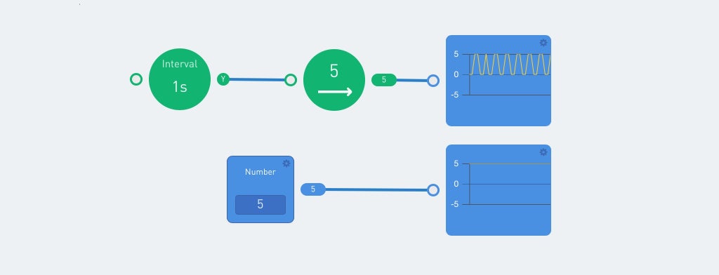
The curve node shows a graph. That is useful to show the different output values. Other useful indicators are the label and indicator node.
Sequence
The sequence runs repeated or only once when the input is 'Y'. This allows for a sequence of actions.
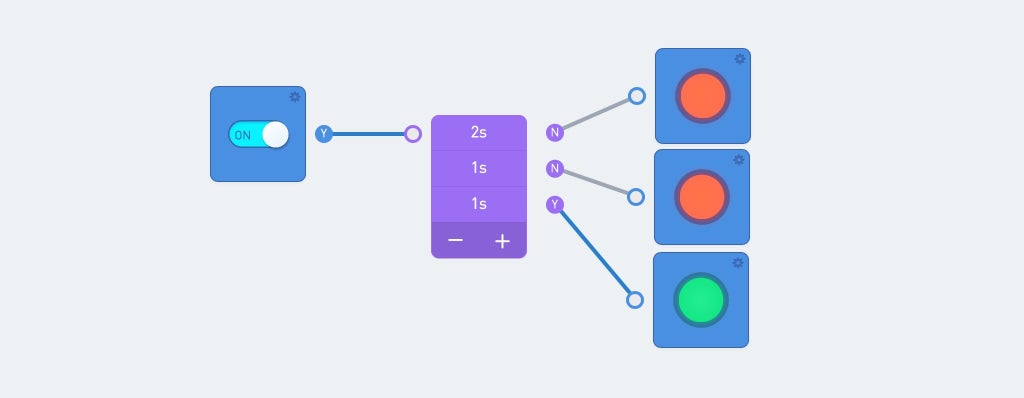
The sequence gets a signal when the switch is turned on. The output of the sequence is passed to an indicator.
Note the color of the lines: The blue lines indicate the current flow. And the circle to the right of a node always shows the current output.
Scale
The scale node translates an input range to an output range. For example 0 to 100 can be translated to a value between 0 and 255.

Values above the maximum of the input range result in a value higher than the maximum output scale! The filter can be used to limit the value.
Valve
This is an node which passes the lower input value if the upper input value is true. This is best explained with an example:
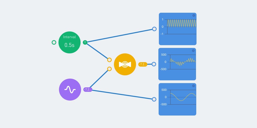
The green interval node switches between 0 and 1 each half second. The ouput of this node is visilbe on the uppper graph. The purple pulse node gives a sinus output, with values between -255 and 255. This is shown on the lower graph.
Both the interval and sinus are input for the valve node. And the output value is 0 when the interval value is 'N'. When the interval value is 'Y', the output value equals the sinus input value. This gives the middle graph.
Step 6: Flow Example


The best way to show the flow programming is by an example. This example uses no Neuron blocks. And everyone can program this after downloading the App. Open the code environment and make a new program. Select '(X)' when asked for a connection, and start programming.
Just drag the required nodes into the program area and connect the lines. Click on de nodes to see the posibilities, and to alter the values/settings.
The output of the buttons is 'N' by default. Pressing a button gives a 'Y' as output. This output is forwarded to a random number generator. This generates a new number (beteen 0 and 100) each time the input has the value 'Y' and passes the output to the next node(s).
The compare nodes require 2 inputs and return the value 'Y' if the condition is met. The upper compare node checks if the value of the A port is greater than the value of the B port. If this is true the lamp turns green. Currently the lower lamp is green, because 21 is below 23.
It requires some practice to program this way. The big advantage is that you don't have to think about the syntax of the code. And each node displays it's output value. In addition, the blue lines represent the data flow.
Step 7: Image Control


There are two Neuron blocks which can be attached to the WiFi block by means of an USB cable: The camera and the microphone/speaker.
Both devices are regular USB devices and can be connected to a PC. The camera requires some additional drivers, but the speaker works as a regular USB speaker.
A camera tab and icon appear inside the app when the camera is attached to the WiFi block. The icon opens a preview window with the camera's image.
There is a photo/camera node inside the camera tab. This takes a picture when there is an input signal with the value 'Y' (true). After placing this node in the program area it has three options (click on the node):
- Photo Frame
- OCR
- Emoticon Test
The photo frame shows the output of the photo node. The next three nodes provide a "photo camera". The camera takes a picture when the button is pressed (this gives 'Y' as output). And this is shown inside the photo frame. The image is stored inside the WiFi block, but is overwritten when a new photo is taken.

It is posible to use the timer for input to the camera, but don't make the interval too short (> 1 second). Else the WiFi block can't handle the data, and hangs for a while.
The OCR node translates images to text. This uses the Microsoft cognitive services. The WiFi block must be connected to the internet, and the App must be connected to the WiFi block.
The next program takes a picture when the button is pressed. This photo is displayed and processed by the OCR node. The output is compared by three text-compare nodes. These check for the values "one", "two" and "three". And each value shows a different image on the LED panel. The output of the OCR node is also displayed by a "label" node. This shows "No" (False) when nothing is recognized.

Blue lines indicate the data flow inside the program. And the 'Y' and 'N' after each node represents it's output value. This simplifies troubleshooting within a program. Unfortunately, the output of the LED matrix is not displayed in the App.
The final camera node option is the emoticon test. This translates faces on an image into a emotion.

The above examples are simple, but they show the basic principle. Extra logic and neuron blocks can be added to create more complex programs
Step 8: Voice Recognition (Microphone)


In addition to the camera, a microphone / speaker Neuron can be connected to the WiFi block. This can be used to record and playback audio fragments. Connecting this Neuron gives an additional "sound" tab in the App.
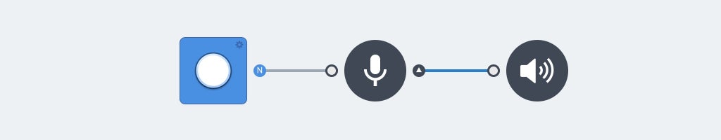
The record node will only record sound if the input is "Y', this requires a button or switch. The recorded audio fragment is the output of the record node. Adding the "play sound" node immediate plays this output. This can be used to make a parrot:
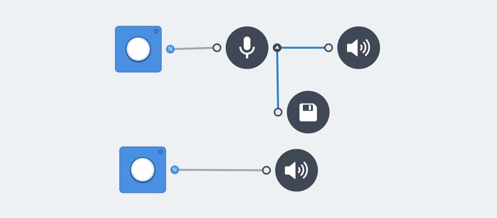
Clicking on the microphone node gives 2 options: "voice to text" and "save record".
The "save record" node saves the audio file on the filesystem inside the WiFi Block. This file is overwritten each time a new recording starts.
The "Play sound" node is capable of playing input audio, but it's also posible to select a sound effect or recorded file. It requires an input trigger to start the given sound. And it stops immediate when the input is 'N' (false). The following example is a kind of dictaphone. The upper button makes a recording and the lower button plays this recording.
The voice to tekst option of the microphone node uses Microsoft cognitive services to translate the recording to text. The label node is capable of displaying the output. The record and play sound nodes aren't required to translate voice into text. But these are useful during programming to check the output.

Debugging of this feature can be done by logging into the WiFi block (advanced feature).
[2018-01-19 23:00:35] [WARN] Request handler 'sound server' was called:
                             {"command":"startRecord"}
[2018-01-19 23:00:35] [WARN] start record
[2018-01-19 23:00:38] [WARN] Request handler 'sound server' was called:
                             {"command":"stopRecord"}
[2018-01-19 23:00:38] [WARN] stop record
[2018-01-19 23:00:38] [WARN] Request handler 'sound server' was called:
                             {"command":"speakerRecognize"
                             ,"fileName":"/tmp/tmpRecord.wav"}
requestSpeech
result: it's a nice day
It's posible to check for multiple words. And the compare node works just like the camera OCR.
Sometimes the same word gives different output. For example: "goodbye" might give one of the following values: "good bye" or "goodbye". This requires multiple text nodes with the same output:

Note: The default speach to text language is English.
Step 9: Voice Recognition (Neuron)


This is an dedicated Neuron to convert voice to text. It accepts 22 commands which are hard-coded inside the block and the Neuron code:
var COMMAND = {'Turn on the light': 3
              ,'Turn Red': 4
              ,'Turn Blue': 5
              ,'Turn Green': 6
              ,'Turn White':7
              ,'More light':8
              ,'Less light':9
              ,'Lights off':10
              ,'Motor Forward':11
              ,'Motor Backward':12
              ,'Speed Up':13
              ,'Speed Down':14
              ,'Love':15
              ,'Smile':16
              ,'Angry':17
              ,'Sad':18
              ,'Rock and roll':19
              ,'Fire Fire':20
              ,'Game start':21
              ,'Winter is coming':22
              ,'Start':23
              ,'Shut down':24};
This block only accepts English. And it requires a correct pronunciation. There isn't much room for error. And even the google voice translate voice output doesn't always activate the corresponding command. But using Google speach remains a good starting point. Start with "Hello Makeblock", "Hello Makeblok" and/or "Helo makeblok". Followed by "winter is comming" or "turn green".
These commands have been used in the code of the first image in this step. The indicator on the right of the upper voice command node is 'Y' (true). This indicates that the command was recognized.
It takes some practice to work with this Neuron. Fortunately, the block repeats the message after receiving one (It contains a speaker and microphone).
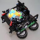
Step 10: Remote Controlled LEGO Turtle


The Neuron Explorer Kit contains 2 DC motors and 2 servo motors. This calls for a robot: A three wheeled turtle. It uses the motors and wheels from the kit with some LEGO parts as frame.
There are 8 beams, in a circular way, attached on top of this frame. These beams give support to the LED strip. Three magnetic Neuron boards are placed on top of the 8 beams. These hold the following neuron parts:
- Wireless Receiver
- Power
- 10 cm cable
- Servo motor driver
- DC motor driver
- LED strip driver
- 10 cm cable
The final 10 cm cable is attached to the ultrasonic sensor, which is placed on the head of the turtle. This head consists of the fourth magnetic Neuron board. Finally, the tail consists of a servo motor, with a lego beam attached to it.
The result looks like "wires and electronics" only, but the turtle shield covers almost all electronics.
The robot can be controlled with the joystick. This requires the WiFi (or Bluetooth) block, the Joystick and the Wireless transmitter. The remote controller requires an USB power source. There is only one power block available, which is inside the robot.
The first image shows a possible program for this robot. The joystick is connected to the DC motor block. Up/down for speed and left/right for direction.
The output of the ultrasonic sensor is compared with the value of 100 cm. If the distance is greater, then the color green/yellow is shown on all LEDs. The colors turn red/orange when the distance falls below 100 cm.
The tail uses a pulse node between -180 and 180. An ABS function makes the negative value positive. This value is passed to the servo motor, and the tail starts wagging.
By combining the neuron blocks and the function nodes it is possible to write more complex programs. The speed of the tail can depend on the speed of the robot or the robot could stop if the ultrasonic sensor measures less than 30 cm.
Attachments

Step 11: Turtle 2.0


The previous LEGO turtle can be simplified by using a piece of cardboard/wood. I've used a piece of 8 mm plywood. Use a jigsaw to create a circle with a diameter of 19 cm. Drill all holes with a 4,8 mm drill. Use the drill and jigsaw to create the square openings. These are for the wheels and the wires.
I've used LEGO parts to attach the Neuron parts to the wooden plate. There are some compatible connectors inside the Explorer Kit. But it's also possible to use m4 bolts for most of the connections.
Two DC motors (with wheels) are attached to the bottom (dark red squares). Just like the rear wheel (black rectangle). A LEGO technic beam is used for additional distance between the plate and the rear wheel.
The three purple squares are for the magnetic Neuron boards. The fourth magnetic Neuron board is used for the head/ultrasonic sensor (orange rectangle).
The red circle shows the location of the LED strip. Use small rubber bands (loom bands) to fasten the LED-strip.
This robot works with the same code as the LEGO turtle.
Attachments
Step 12: Software Internals


Programming the Neuron blocks is easy, there is no need to write any code. The following information is therefore only for the advanced user. It provides some insight into the operation of the Neuron product.
The Makeblock Github page contains Neuron code. You can download it and explore the code. It's written in Javascript and uses nodeJS.
The WiFi block should be connected to the internet. When the App connects to the SID of the WiFi block it receives an IP address from the WiFi block. The WiFi blocks now acts like a gateway.
The WiFi block's IP address is 192.168.100.1. There is a webserver running on port 80 which shows a configuration interface (password = makeblock). This allows to change various settings and options.
You can change the timezone and/or the WiFi SSID. But be careful, there is little documentation about the other settings.
The Services/Network shares tab shows all network shares. I've made an additional share "Server" to the "/tmp/run/mountd/mmcblk0p1/neurons-server" folder. This folder (and sub-folders) contains all log-, sound- and image-files.
This makes it possible to browse through all files with the Windows file explorer. Opening the "\\192.168.100.1\Server" share gives read-access to all files of the Neuron engine. Including the server log file:
device uuid:6A1BC6-AFA-B4B-C1C-FED62004
try mqtt.connect
connected to iot cloud ok...
[2018-01-19 22:56:43] [WARN] serverLog - Request handler 'sound server': {"startRecord"}
[2018-01-19 22:56:43] [WARN] serverLog - start record
[2018-01-19 22:56:45] [WARN] serverLog - Request handler 'sound server': {"stopRecord"}
[2018-01-19 22:56:45] [WARN] serverLog - stop record
[2018-01-19 22:56:46] [WARN] serverLog - Request handler 'sound server': {"speakerRecognize"}
requestSpeech
result: hello
The config.js file contains all settings. This includes the Microsoft Keys and the current log-level. These can be altered, but always keep a copy of the original file.
The default log level is "WARN". This can be altered when needed:
* `loglevel`: the loglevel to set, will not print the log which priority lower than set.
  * currently support loglevel
    * **TRACE**,
    * **DEBUG**,
    * **INFO**,
    * **WARN**,
    * **ERROR**,
    * **FATAL**
I've made a read-only network share. A read-write share makes it posible to place images (jpg 640x480 24bits) and sound (wav) files inside the WiFi block. These can be used within the App.
There is also a ssh server running at port 22. This makes it posible to logon into the Linux shell. Use Putty to connect to 192.168.100.1 and login with the root user and password makeblock. But be vey carefull.
The WiFi blocks runs OpenWrt. This is a Linux distribution for embedded devices. The Neuron software is located in the "/tmp/run/mountd/mmcblk0p1/neurons-server" directory.
It is possible to program most of the Neuron blocks with the mBlock software. This requires version 4.0.4 of the software. The Microsoft services aren't available in this scratch version. The voice recognition Neuron, which doesn't require these services, can be used. The mBlock Version 5 doesn't support the Neuron blocks at this moment (januari 2018).
The Neuron code blocks are available in the Robots (blue) part. And the mBlock software has the advantage that not only the connected blocks can be used. It makes no sense to use blocks which you don't have, but this makes it possible to write code without any Neuron blocks connected.
The default password should be changed when the Neuron is used on a open WiFi network.
Step 13: Hardware Internals


This hardware information is for background information only. It has not been verified by Makeblock!
Most hardware from Makeblock products is well documented. But there isn't much hardware information about the Neuron product. There are some images on Kickstarter but this shows the internals of a prototype. This one only has one USB connector, and the actual product has two USB connectors.
The webserver inside the WiFi block reveals the actual hardware used for this block. It's a MediaTek LinkIt Smart 7688. The key features of this board are:
- Runs OpenWrt Linux and supports application development in Python, Node.js and native C programming languages.
- Uses a MT7688AN as a standalone MPU and supports two operation modes – IoT gateway and IoT device mode
- Supports Wi-Fi, USB host and SD cards.
- Pin-out for PWM, I2C, SPI, UART, Ethernet, and I2S.
- Supports up to 256MB RAM with additional SD-card storage.
The Linux file systems shows the internal disk storage:
root@makeblock_linkit:~# df -h
Filesystem                Size      Used Available Use% Mounted on
rootfs                   17.9M    644.0K     17.3M   4% /
/dev/root                12.8M     12.8M         0 100% /rom
tmpfs                    61.7M    812.0K     60.9M   1% /tmp
/dev/mtdblock6           17.9M    644.0K     17.3M   4% /overlay
overlayfs:/overlay       17.9M    644.0K     17.3M   4% /
tmpfs                   512.0K         0    512.0K   0% /dev
/dev/mmcblk0p1            1.8G    101.4M      1.7G   5% /tmp/run/mountd/mmcblk0p1/
There is a disk volume named mmcblk01 inside the block. This name is mostly used for memory cards. It looks like there is a 2 Gbyte SD card inside (1.7 Gbyte + 256 Mbyte for the LinkIt 7688).
The pogo pins have 4 connectors: One for VCC, one for ground and two for communication. The Neuron blocks probably communicate with the I2c protocol. There must be an Arduino compatible board inside each neuron.

Participated in the
Design For Kids Challenge

Participated in the
Voice Activated Challenge


