

Introduction: Sarah the Simplest Arduino Robot

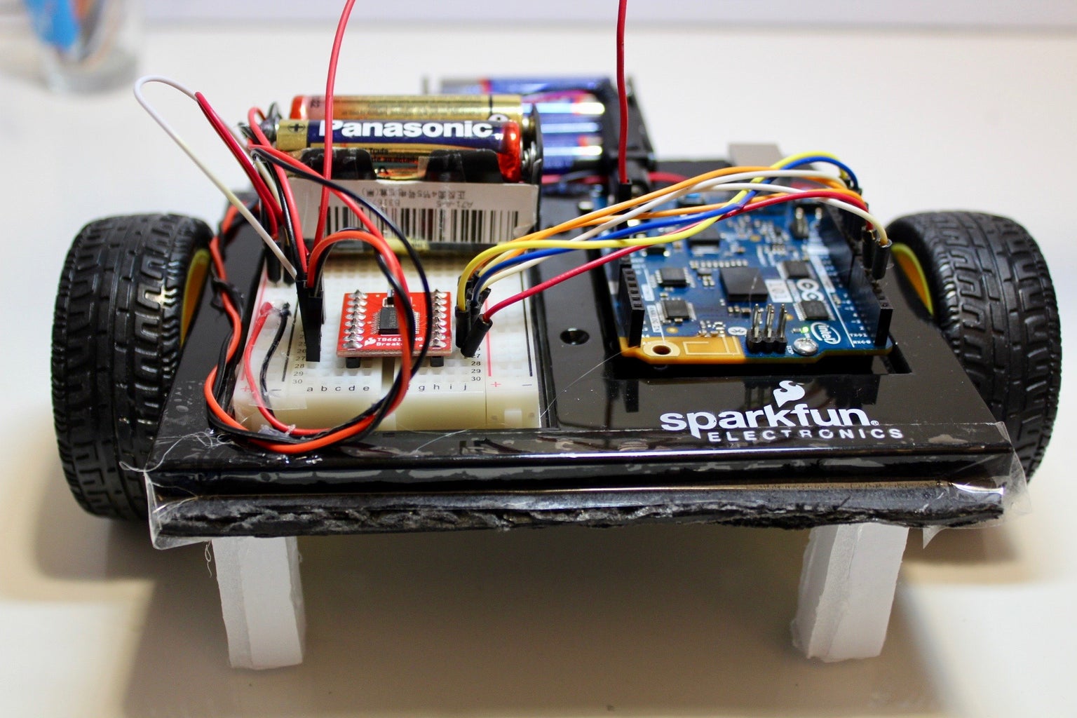


Sarah is a small, quick, and simple Arduino robot for beginner makers. She uses a differential drive to maneuver. She also uses the Dual TB6612FNG, capable of drawing 1 amp, motor driver to control the motion of the two wheels.
I wanted to make a cheap and simple robot for those makers whoa re just getting into the hobby, so as to make something fun to play with without breaking the bank or pouring countless hours into.
Step 1: Tools and Materials

Electronics
- Arduino 101 or Arduino Uno
- Breadboard
- Dual TB6612FNG 1 Amp Motor Driver Board
- Jumper Wires
- DC motors and wheels
Chassis
- Foam Board - 15cm x 15cm
- Battery Holder and 8 AA batteries
Tools
- Glue Gun
- Clear Tape
Step 2: Glue the Motors to the Foam Board


- Mark the halfway line of the 15x15cm square foam board with a pen.
- Align the centre of the rotating axle of the motor to the halfway line on both sides and glue it with a hot glue gun.
- Attach the wheels to the motor when the hot glue has solidified. It will fit in snuggly.
Step 3: Making the Pillars


- Balance the robot on the two wheels and measure the height of the robot below the foam board.
- Cut a foam board sized for the measured height and glue two pieces of it together, to make a pillar.
- Glue the pillars onto the four corners of the robot's base, to make it balance.
Step 4: Secure the Arduino Board to the Chassis


- Tape the front edge of the Arduino and breadboard holder to the leading edge of the car, wrapping it around the chassis. Cut off any excess tape.
- Tape the trailing edge of the Arduino and breadboard holder to the foam board chassis and cut off any excess tape.
Step 5: Adding the Battery Holder


- Glue the battery holder with the barrel jack connector to the front of the chassis with the hot glue gun. It will stick out a bit, but that's alright.
- Secure it by further gluing edges of the battery holder onto the chassis with the hot glue gun.
- Place two of the AA batteries on the battery holder with the two exposed wires, and tape these batteries securely to the holder.
- Add two small beads of glue onto the tape holding the battery and adhere it to the breadboard with hot glue.
- Plug in the red wire on the battery holder to the red power rail and the black wire on the black power rail.
- Secure the wires using with hot glue and tape onto the breadboard.
Step 6: Cable Management


- Twist the two motors wires together.
- Glue both wires onto the chassis to a length short enough so that the wire does not get caught by the wheels with a hot glue gun.
- Make sure at least one of the batteries is unplugged, then glue the battery holder wires onto the front of the breadboard and Arduino Holder with a hot glue gun.
Step 7: Wiring the Motor Driver


- Connect the first motor's pins to pins 4 and 5 of the motor driver board.
- Connect the second motor's pins to pins 6 and 7 of the motor driver board.
- Connect the motor driver board's pin 1 to the red power rail and pin 5 to the black power rail.
- Connect the Arduino's pins 8 to 12 to the motor driver board's pins 11 to 15.
- Connect the Arduino's pin 5 to the motor driver boards's pin 10.
- Connect the Arduino's pin 3 to the motor driver board's pin 16.
Step 8: Coding

The motor driver board uses two pins per motor to control the direction and one pin to control the speed by using PWM signals. In addition to the speed and direction pins, it also has one pin for standby mode, where both motors are not being supplied power and therefore acts as an emergency stop function.
Setting both pins to HIGH or LOW makes the robot stop. To control the direction of the robot using the two direction pins, set one of the direction pins as HIGH and the other direction pin as LOW. To make the motor spin in the opposite direction,
Compile and upload the following onto the Arduino and then remove the printer cable once it is uploaded.
//motor A connected between A01 and A02
//motor B connected between B01 and B02
int STBY = 10; //standby
//Motor A
int PWMA = 3; //Speed control
int AIN1 = 9; //Direction
int AIN2 = 8; //Direction
//Motor B
int PWMB = 5; //Speed control
int BIN1 = 11; //Direction
int BIN2 = 12; //Direction
void setup(){
  pinMode(STBY, OUTPUT);
pinMode(PWMA, OUTPUT); pinMode(AIN1, OUTPUT); pinMode(AIN2, OUTPUT);
  pinMode(PWMB, OUTPUT);
  pinMode(BIN1, OUTPUT);
  pinMode(BIN2, OUTPUT);
}
void loop(){
  move(1, 255, 1); //motor 1, full speed, left
  move(2, 255, 1); //motor 2, full speed, left
delay(1000); //go for 1 second stop(); //stop delay(250); //hold for 250ms until move again
  move(1, 128, 0); //motor 1, half speed, right
  move(2, 128, 0); //motor 2, half speed, right
  delay(1000);
  stop();
  delay(250);
}
void move(int motor, int speed, int direction){
//Move specific motor at speed and direction
//motor: 0 for B 1 for A
//speed: 0 is off, and 255 is full speed
//direction: 0 clockwise, 1 counter-clockwise
digitalWrite(STBY, HIGH); //disable standby
  boolean inPin1 = LOW;
  boolean inPin2 = HIGH;
  if(direction == 1){
    inPin1 = HIGH;
    inPin2 = LOW;
  }
if(motor == 1){
digitalWrite(AIN1, inPin1);
digitalWrite(AIN2, inPin2);
analogWrite(PWMA, speed);
}else{
digitalWrite(BIN1, inPin1);
digitalWrite(BIN2, inPin2);
analogWrite(PWMB, speed);
}
}void stop(){
//enable standby
digitalWrite(STBY, LOW);
}Step 9: Testing

- Add the remaining batteries onto both battery holders.
- Connect the barrel jack from the battery holder onto the Arduino to power it.

Participated in the
Makerspace Contest 2017

Participated in the
Invention Challenge 2017


