

Introduction: Scanning Laser Microscope With Arduino


Hello!
I'd like to share my latest project, a scanning laser microscope with you.
Some words concerning the principle: The pinciple is quite simple. The laser beam is focused on the object and the reflective light is being measured with a photodiode (in my case a BPW34). To focus right the current through the focusing coil is varied. The position of the object is changed by two Speakers, which are driven with different voltages. The speaker-membrane is moving and therefore the object-table, which is connected with the membrane is moving too. With this way of moving head you can reach movements down to µm.
Step 1: The Cd-drive


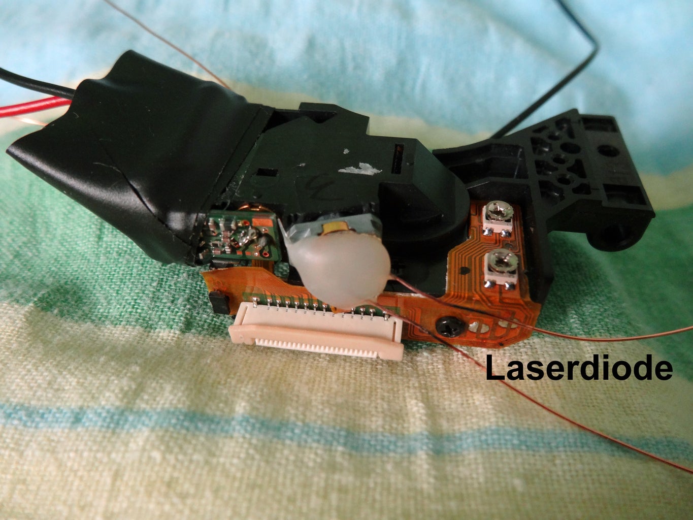


A Commercial cd-rom-drive is ideal for our purpose. It combines everything we need, a laser-Diode, a lens with variable Focus and a photodiode. In my case I've changed the build in photo Diode with a lot of Pins against a single BPW34 with just two Output-Pins. Older cd-drives are suitable for the laser microscope because they aren't so miniaturized like modern drives. I use a cd-rom-drive instead of a DVD- or bluray-drive, because in the early days of this technology the pins have been larger and more separated than in modern drives...
You'll have to find out the two Pins for the vertical coil and the laserdiode. If you replace the built-in photodiode against a larger model you'll have no problems with soldering.
The laser-Diode needs a constant current, about 80mA. This can be easily realized with a LM317 and some resistors.
Step 2: The Speakers for the X/y-movement
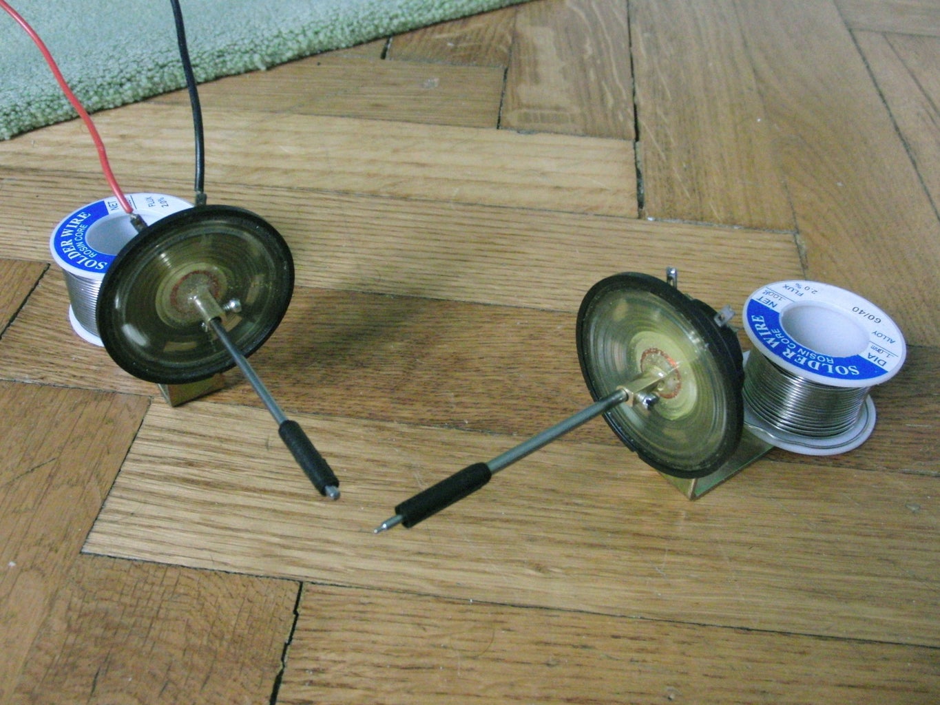


You'll have to look for suitable speakers with little movement. I took some small ones with a resistance of 24 Ohm. A metall bar is glued to the membrane. At the end of the bar a small piece of copper-foil (0.5 mm thick) is soldered with the bars.
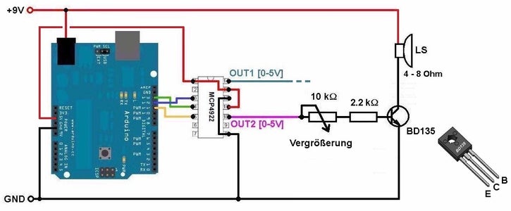
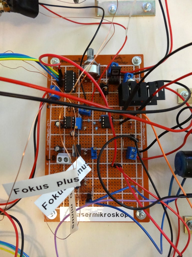
To drive the Speakers I use a MCP4922-DAC. It offers two voltages between 0 and 5V. With some resistors and a Transistor I'm able to vary the current through the Speakers up to 250mA. With a potentiometer the magnification of the microscope can be changed. The larger the value of the potentiometer, the higher the magnification.
Step 3: How to Focus


Focusing right is a difficult work because we are speaking about µm.
Usually cd-drives use photo-diodes with more than 4 areas (ABCD in the Picture). With those signals you're able to find out the Focus quite easily. It's in the focus, when the Signal (B + C) - (A + D) gets zero.
Using a single photodiode we just get one signal. But don't worry, there's another way to find the right Position of the coil. Changing the current through the focuing-coil you'll see, that the Output-voltage of the photodiode first increases, going through a Maximum and then decreases. Exactly in that maximum the laserbeam is focused right. To make this easier, you should use a 10-turn-potentiometer (in my case a 100Ohm-type parallel to a fixed 100Ohm-resistor to get 0-50 Ohm).
If no object is on the moving-table, I get voltages in the range of 0.2V. If something is lieing on the table, the voltage slightly increases. The arduino is able to read voltages between 0 and 5V. Therefore we first have to eliminate the Offset (0.2V) and second we have to amplify the signal up to 100 times. For this purpose I use a LM358. Before scanning I turn the gain-potentiometer to get voltages as high as possible.
Step 4: The Visualization of the Data


You'll have two ways of visualization, with the Software processing or with a TFT-display. I recommend a 480x320 Display (no touch), which you can get on ebay for less than 10 USD.
If you prefer processing you'll have to send the data in the following way:
Serial.print(xPos);
Serial.print(",");
Serial.print(yPos);
Serial.print(",");
Serial.println(value);
Using the TFT-Display you'll need the UTFT-library. Just search for "rinky-dink electronics" (http://www.rinkydinkelectronics.com/library.php). There you download the UTFT-library for arduino.

Step 5: The Complete Setup & Code

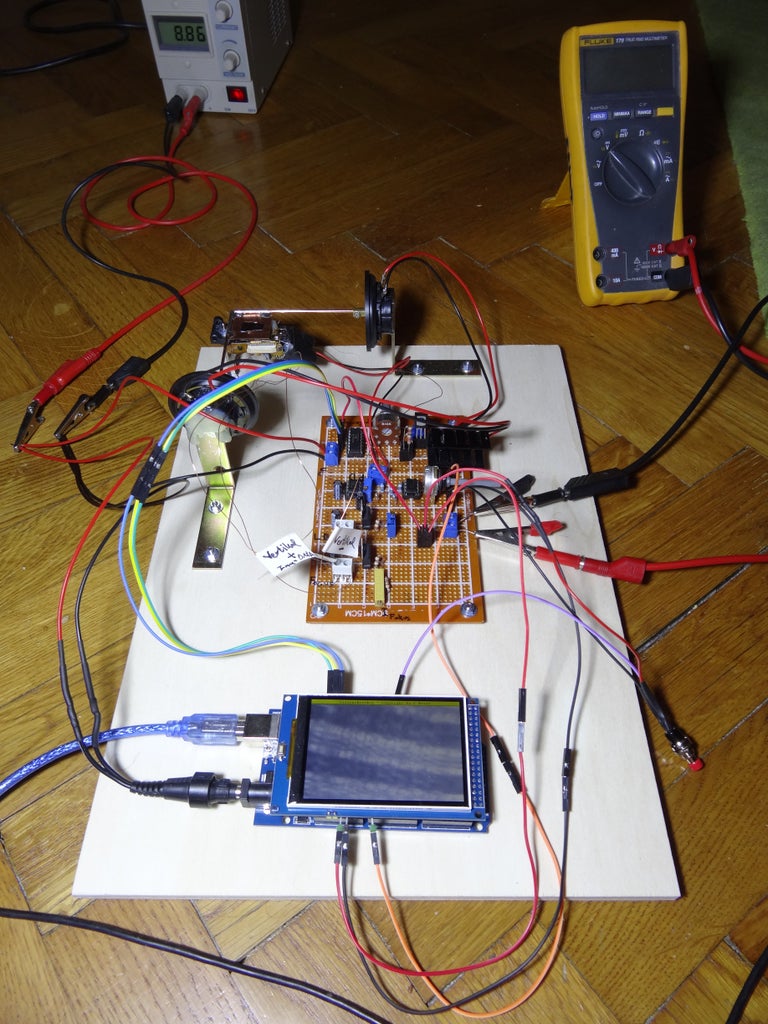


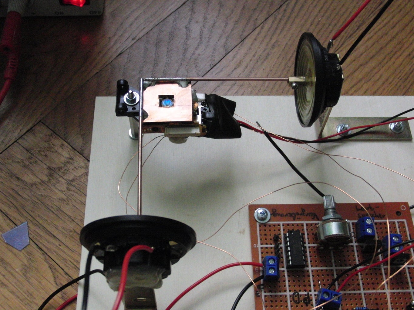
Finally everything is mounted on a wooden plate and all the outputs and potentiometers are mounted too. The only additional parts you'll need are a multimeter for controlling the photodiode-voltage and a power supply (9V, 0.6A). If you want you can take a 7.4V lipo and a DC DC step up module to work everywhere you want without the need of a Computer or power supply.
Step 6: The Calibration


To be able to estimate the magnification I bought a cheap calibration slide on ebay. The finest scale is 0.01mm, so 10µm. With this slide put on the moving-table you can easily find out the magnification.
Step 7: The Results
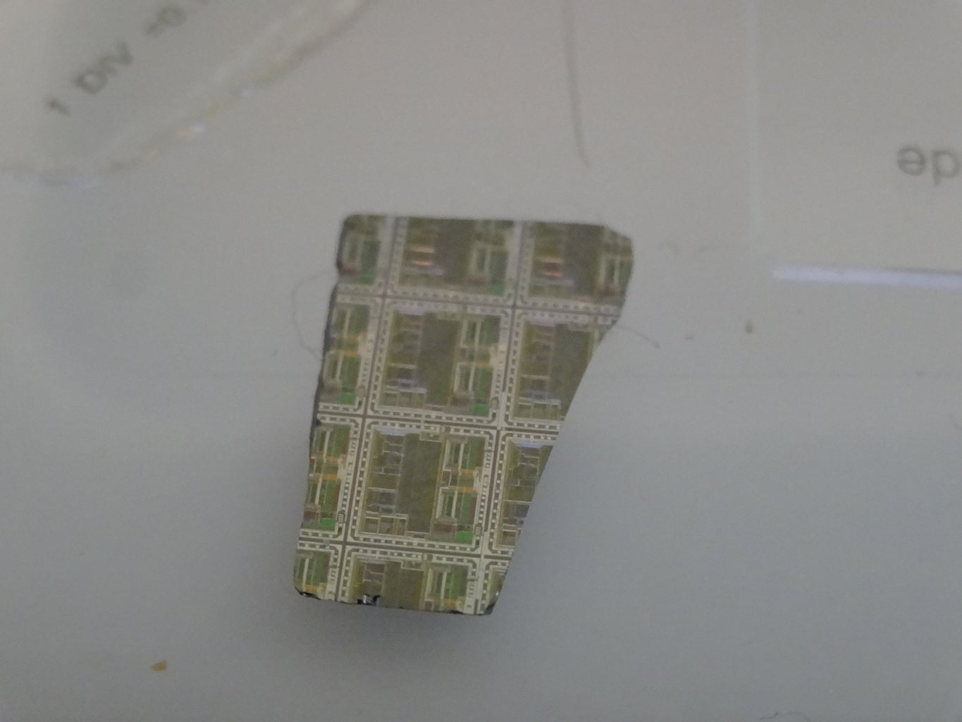


Luckily I found a piece of a waver with very tiny structures. But the main Goal of my Project was to visualize the pit-structure of a compact disc. For this project I had to cut an old windows-CD into pieces (so window's isn't quite worthless ;-) ).
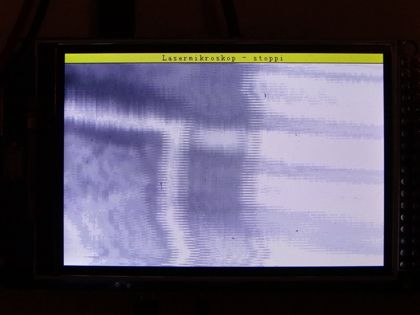
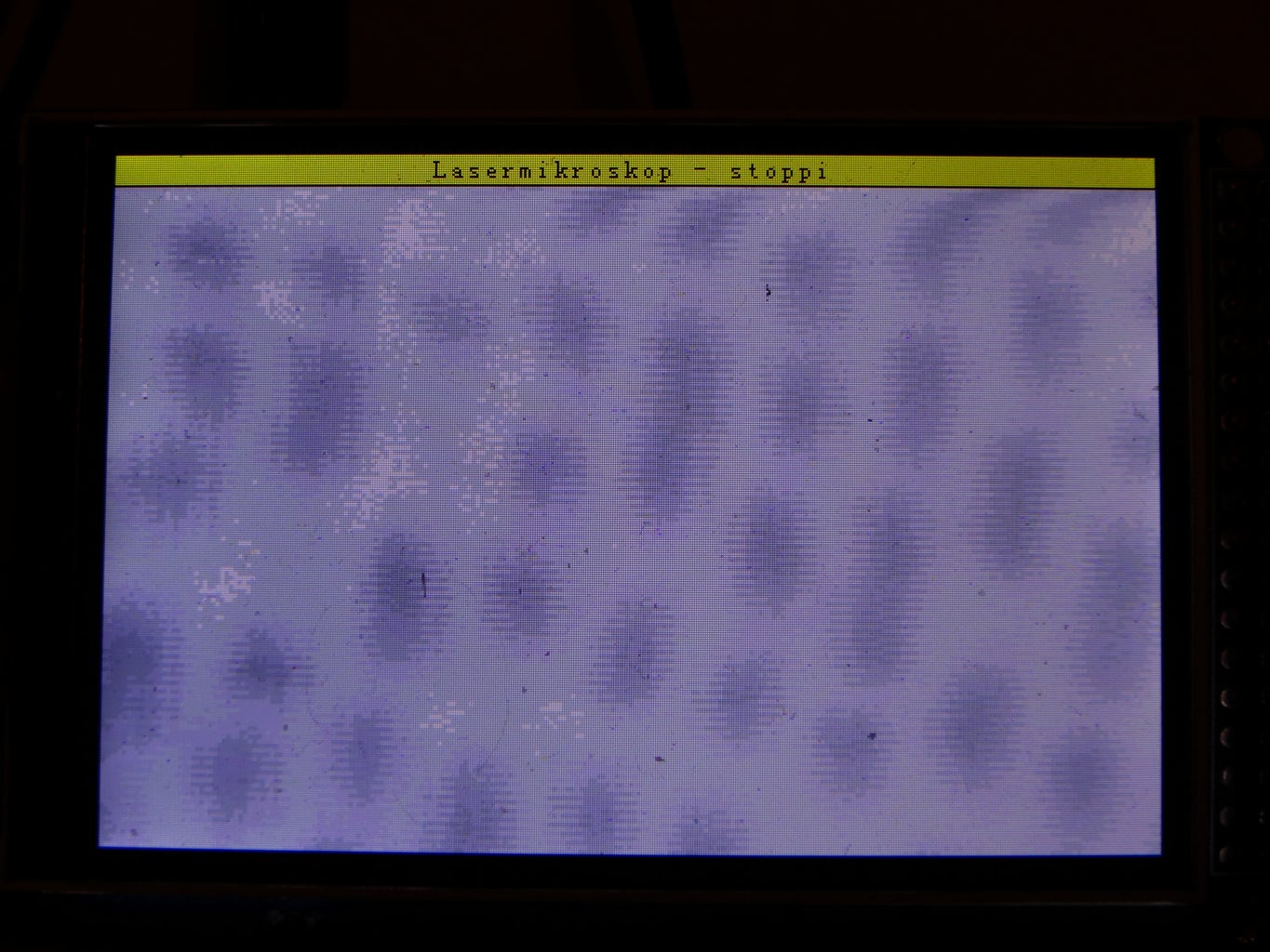
Voila', there are the 0's and 1's. To get this resolution I had to increase the resistance of the potentiometer nearly to the maximum.
I hope you've enjoyed my work. Maybe you'd like to take a look at my YouTube-channel (https://www.youtube.com/user/stopperl16/videos)
more physics projects: https://stoppi-homemade-physics.de/

Runner Up in the
Microcontroller Contest 2017


