

Introduction: Self Balancing Bot Using PID Control System


A self balancing bot is a two wheeled robot. Normally the robot can pitch and fall, but using information from IMU (inertial measurement unit) sensors, it corrects its pitch angle and balances itself.
Step 1: Arduino Developement Board.

Arduino is a Developement board based on different ATMEGA microcontrollers. For example, ARDUINO UNO is based on ATMEGA328P Microcontroller. The Microcontroller is used as the brains of the robot. All the data received from the sensors is processed by the microcontroller and it also sends the required output signal.
Step 2: MPU6050 IMU

An IMU is an Inertial Measurement Unit. In this case, we will be using MPU6050 IMU which contains an accelerometer and a gyro sensor. we will combine the RAW values from both accelerometer and gyro and combine them using complimentary filter to get accurate angles.
Step 3: DC MOTORS and WHEELS

We need two DC motor for locomotion. The motors should be at least 300 RPM and choose appropriate wheels. Remember to have snug fit between the wheels and motor shaft. Also make sure that the motors are properly mounted to the frame and is tight and snug. We need to avoid loose screws otherwise out bot may not even balance.
Step 4: Motor Driver

Know the current ratings of your motor and choose proper motor driver. In this case, we will be using L298N motor driver. DC motor drivers are basically embedded form of the circuit know as "H- Bridge". To know, how H-Bridge works, take a look at the video above.
Step 5: Batteries

There are many types of batteries that can be used for this project, but the most appropriate choices are 2S or 3S Li-po batteries, 18650 battery pack or AA battery pack. Make sure your motor driver can deal with the voltage of your battery.
Step 6: Frame or the Chassis

There are some things that you should make sure when you're choosing the proper chassis
1) It can take the weight of all the components easily.
2) Should be rigid ,strong and not at all floppy.
3) Motors can be mounted securely.
4) Easy to build :-).
Step 7: More Stuff


Breadboard, jumper wires, hot glue gun (maybe) , screwdrivers, zip ties et cetera.
Step 8: Explaining PID and How We Use It Here.
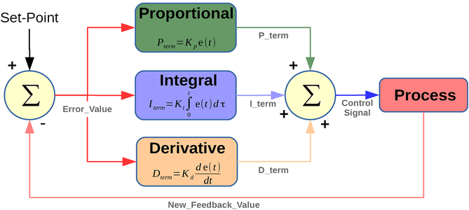
PID stands for Proportional, Integral & Derivative. Basically, PID is a feedback loop control system, which means the output of the algorithm is the fed back as an input to improve accuracy and minimise the Error. What actually happens is first the current error is knows(p-term), then very small error(close to the target value) is know(I-term) and finally what may be the error after some time (d-term) is calculated and then the summation of all these errors is used to create the Correcting signal. The error value is again fed back to the PID system for corrections. This cycle goes on and on.
In this project we use PID to create correction signals from error in angle values. The target angle is 0 degrees. the angle value goes through the PID algorithm and the correction value is created as the sum of all the 3 terms.
PID= P+I+D;
The value of PID can be negative too because angles can be negative, but we need absolute values because we need a value between 0 to 255 for the analogWrite() finction that controlls our motor. SO, for that we use abs() function to make PID values absolute. Remember the higher the error, the Higher the PID value.
Different bot designs will balance well with different kp,ki and kd (PID constants). Tune them according in the code. Trial and error is the Key.
To know more about PID, take a loot at the link below.
Step 9: The Circuit

The circuit is Shown above. However, here are the wiring details.
1) MPU6050:-
gnd----------->GND
vcc----------->5V Arduino
SCL---------->A5
SDA---------->A4
INT------------>D2
2) L298N Motor Driver.
gnd------------->GND + battery -ve
12V------------->Battery +ve
5V--------------->5V Arduino
IN1,IN2,IN3,IN4-------->D10,D9,D6,D5.
A,B,C,D------------->MOTOTRS.
Step 10: Assembly
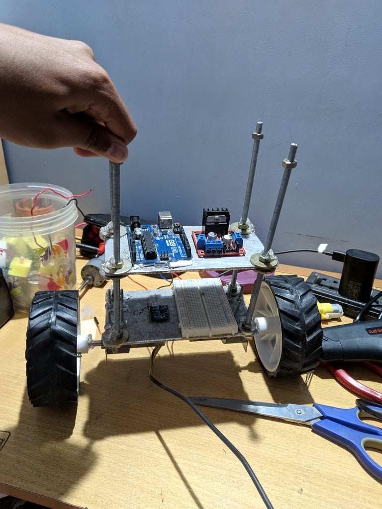


Place the Circuit on your chassis. Again, make sure that you place everything properly and it should not flatter here and there. Use hot glue to secure every loose screws and dangling components. use breadboard for simplifying the circuit and finally use zip ties for wire management.
Step 11: Code
There are 2 code attachments. One is for measuring the Angles from MPU6050 and can be used to understand the Complimentary Filter. The other code is for the Robot. The code is explained using proper comments and doesn't require to add any third party libraries. The only Library used is wire.h which is an inbuilt library.
Happy Making :-)


