

Introduction: Send Numeric Data From One Arduino to Another
Introduction
by David Palmer, CDIO Tech. at Aston University.
Did you ever need to send some numbers across from one Arduino to another? This Instructable shows how.
You can easily test it works by simply typing a string of numbers to send at the Serial Monitor terminal, and see the numbers come back out at a second Serial monitor connected to the second Arduino. You can even use a Bluetooth link.
What it does
Two Arduino programs (sketches in Arduino speak) need developing, one a Master program to connect to the host computer running the Arduino Serial Monitor, one to act as Slave to receive the serial message from the Master, decode it and send it back. The slave is optionally capable of displaying the numbers it's dealing with onto a second IDE's Serial Monitor - just in case you want to use this. It may help getting things working in the first place, and help you if you decide to make any changes to the programs to suit your own requirements.
Equipment
- 2 Arduino's
- 2 USB leads
- patch wires (as required)
- 1 PC/laptop loaded with Arduino IDE (available as free download from the Arduino.cc website)
Step 1: Setting Up - Set Your Hardware Up First
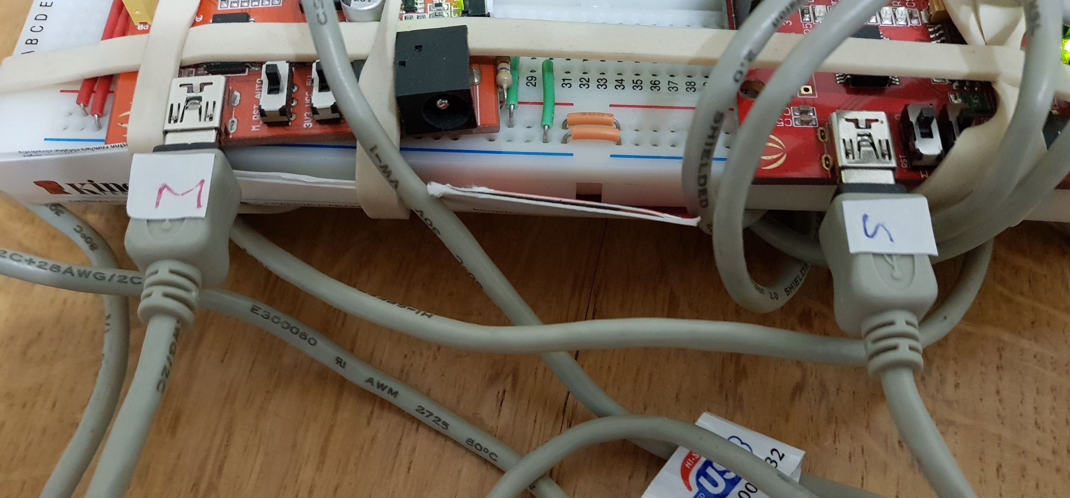
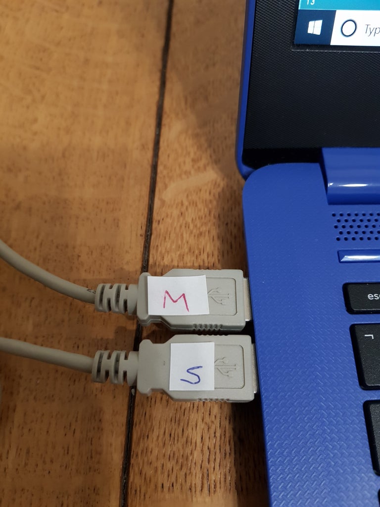
Plug the 2 Arduinos into 2 USB ports on your computer.
Tip, it’s a good idea to label them as M and S (master and slave) so you don’t get into a muddle later (as shown in the 2 photo's here.)
Step 2: Setting Up - Set Your Screen

The best thing is to set up your screen so that you have
- the IDE loaded with the Master program on the left and
- that with the Slave on the right.
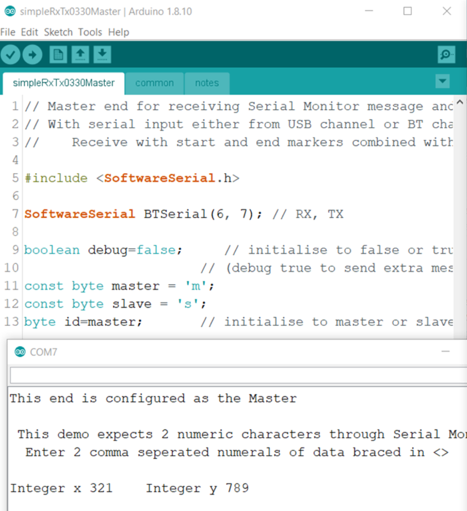
Keep the Serial Monitors for Maser and Slave on the left and right too as shown in the screen shot here.
Step 3: Set-up the Master End, Then Connect Together - Part 1
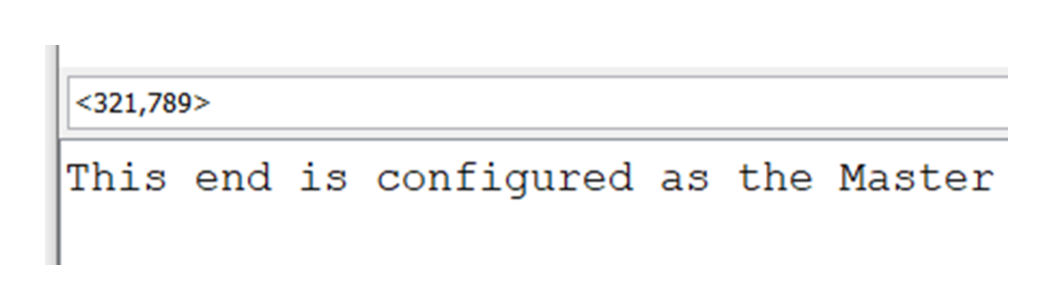
When you set up your Master End Serial Monitor to send two numbers, you must always use the start, and end, delimiter characters < and > , and the comma separator character as you see here.
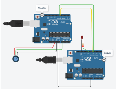
You now need to connect the 2 Arduino's together over serial. This is done with two patch wires.
I used green and yellow
- Take the yellow first, this must plug into D6 in one Arduino and D7 in the second one
- Then the opposite for the green wire, D7 on the first and D6 on the second Arduino.
Alternatively, if you have something available like a pair of Bluetooth modules - like HC-05's - these will also work to give you exactly the same effect as the wires above.
Step 4: Set-up the Master End, Then Connect Together - Part 2

We are making use of the Software Serial library. Further information is available with this link https://www.arduino.cc/en/Reference/Libraries .
You can see it called-out on line 7 of either of the programs. It configures pins digital 7 and 6 as TX and RX (transmit and receive). This is how the data will travel out of the Master Arduino through the green wire into the Slave, and, when the Slave program in the second Arduino has finished its work, back through the yellow wire. At the bottom of the same illustration (in the Serial Monitor window) you can see the data we transmitted has now successfully gone round the loop described here, and come back into the PC as the pair of integers nicely separated out.
Step 5: Overview of the Sketches / Programs - Structure of the Program

Layout
Like in all Arduino sketches there are 3 basic parts:
- The Declarations
- The Setup
- The main Loop
As often occurs, we have made use here of a 4th section which is the addition of 'Functions'. If you are not familiar with using Functions you can Google for "Arduino functions" and you will find explanation sites like the example in this link: www.tutorialspoint.com/arduino/arduino_functions.... .
We have also made use of tabs to separate the program into more manageable blocks.
The three blocks we have used can be seen at the top of each illustration of the IDE windows above:
- simpleRxTx0330Master
- common
- notes
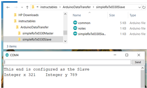
These are actually separate files inside the program's folder, as you can see in this Windows Explorer view of the Slave program's files.
There is a very good reason why we have done this.
- As we were building up the program we came to realise that most of the program for the Master was the same as for the Slave.
- We ended up pulling all the common parts into a tab, which we therefore named "common", and then each time we had debugged a part (tested it, and were satisfied it worked OK) we just copied-and-pasted that whole tab across from Master to Slave, or visa versa.
- The notes tabs also happen to be identical, as the design is generic.
None of the functions are called from setup, they are all called from loop, so we have created them after setup but before loop.
Step 6: Top Down Design.
It is a good idea to design your sketch starting with a definition of what you want to do.
Once you have this you can start making the sketch do those things. Generally if there's a detail you don’t know how to do yet, just make it a function, and leave the creating of the function until later.
This follows the good design philosophy, taught in many Universities, called CDIO (If you don't already know this one you can Google it, and find sites to explain it like: http://www.cdio.org/s .) This basically says: Don't start the Design before you've got the Concept clear. Don't start the Implementation until you've got the Design clear. Don't expect it to Operate before you've got the Implementation clear. C first, then D, I, and O. At each subsequent stage you iterate (go back round the loop(s), so once you're happy with your initial Design loop back and check that it still meets the Concept, and update the C if you need to. And so on, so even when you have got to Operating, go all the way back to the top, and again see how the C is looking now, then the D and I, and make and check all changes as necessary. With programming sketches this works just the same if you Top-Down design.
Step 7: Concept and Design - Part 1
The Concept here looks like the outline requirements stated in the 'notes' tab.'
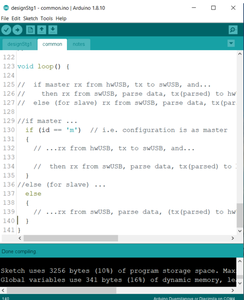
The Design could look like an early version of the loop, which matches the notes tab and could look something like you see in this figure
See how I like to start by actually CTRL-C copying the comments into the head of the loop first, and then start filling in the blanks with commands that will do those things.
This actually compiles OK as you can see at the bottom of the screen in the figure. That's reaching from CDIO stage D to I, and as we develop the code its a good idea to keep going round this D-I loop.
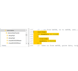
Now it's time to go down to the next stage, there's a comment there that says we're going to: //receive something from the hardware USB, then we're going to transmit that onto the software serial channel. We write this code to make that happen - lines 133 to 138 shown here in yellow highlighter
Step 8: Concept and Design - Part 2
The two first two functions we introduce here are (recv() and tran() to do the receiving from the hardware port and the transmitting to the software port - hence calling them with the 'hw' or 'sw' parameters shown.
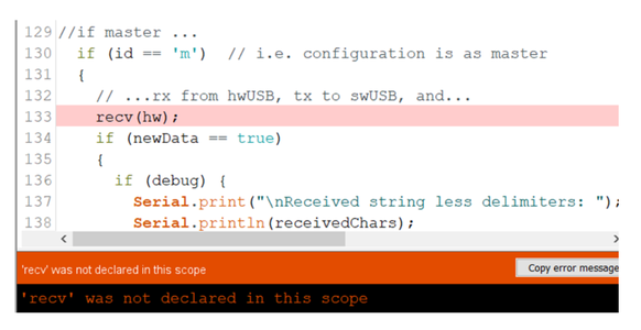
In addition to them, we have added a test on a global variable called newData. This is a flag we will set inside the "void recv();" function. When a message has been received this variable is flagged from false to true . We do this so that we only transmit a message if one has been received (flag ==true) in line 134. And once we have transmitted our message that's 'job done' so we clear the flag back to false again in line 137.
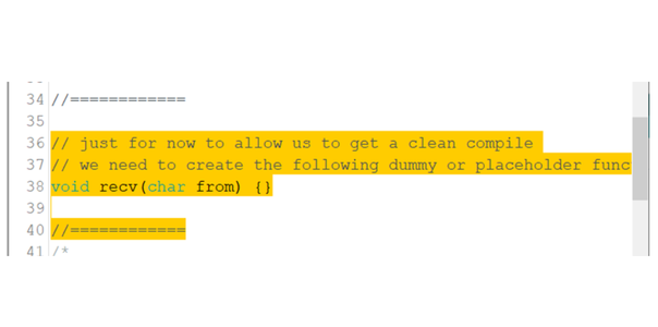
Again we can check compile (D to I), and this time we have a 'not declared' error message (shown). This is telling us we haven't declared the recv(); function. We plan to do this later, so just for now to allow us to get a clean compile we need to create a dummy or placeholder function, as shown next.
Again we can check compile (D to I), and this time we have another 'not declared' error message for the tran(); function. This needs a similar stub creating. Again we can check compile (D to I), and this time we will find this works perfectly; so far so good.
Step 9: Finish the Main Loop: A) Receiving From USB, B) Receiving From Slave Arduino.
There is one final piece we have added to finish this part off which is to add some debugging code.
There is another Instructable on debugging sketches which may be referred to to understand what we have done here and why. Refer to the Instructable "How to build and test Arduino sketches until they work"
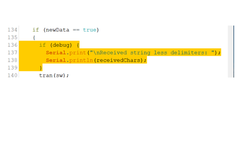
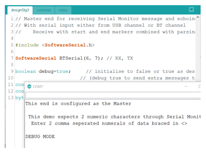
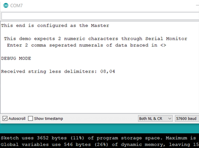
So these debug lines [136-139 shown] are added-in next in the main loop and, lo-and-behold, you can test them in the Master end by making the debug variable true, and Compiling (I), then if you connect an Arduino up you can Upload, open the Serial Monitor and see if what comes back into the Serial Monitor is as shown here (do you see "DEBUG MODE" message is added?)
Step 10: Receiving and Handling the Data in the Slave Arduino
Receiving from Slave Arduino
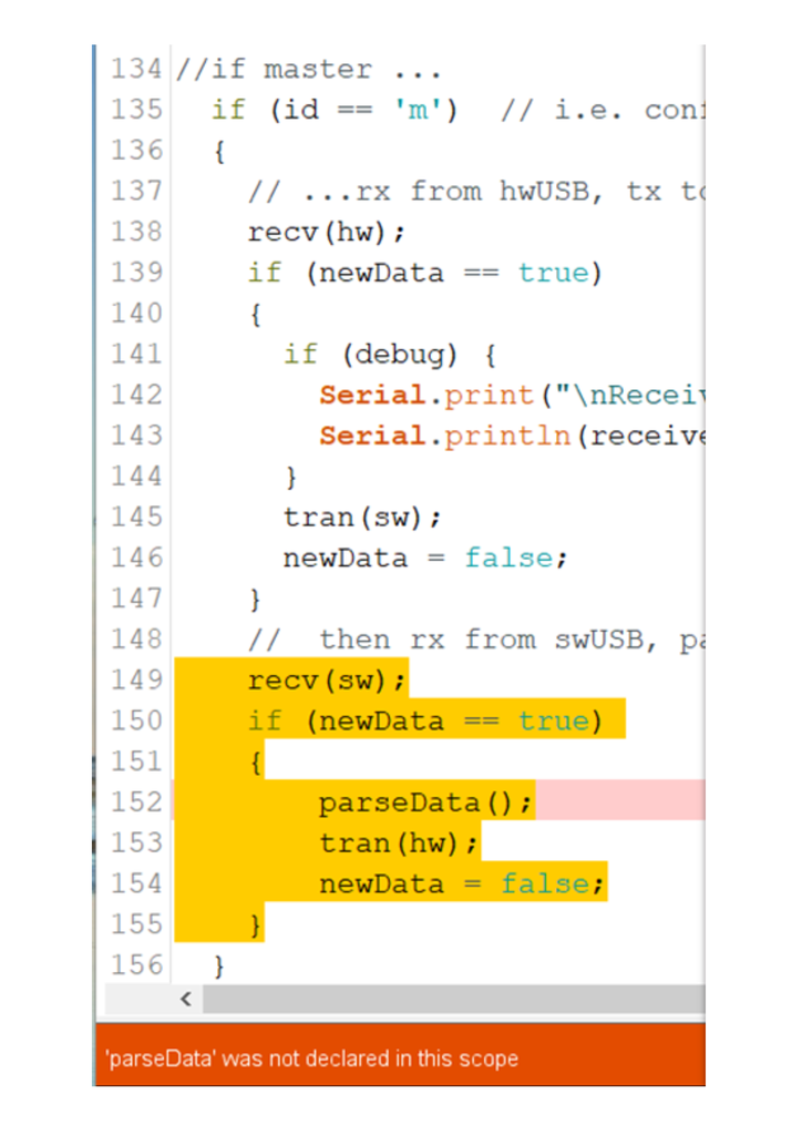
Add the necessary code for the second channel to the main loop , the software serial receiver as shown - lines 149 to 155.
Can you see that the structure is loosely based on what we wrote above for the Master case?
Also you will see that we get a compiler error, another undeclared function - this time parseData(); - so we need to make a stub for this too, before we can run an error-free test compile.
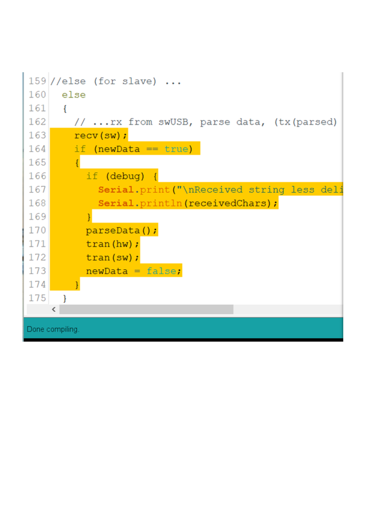
Handling the data in the Slave Arduino
Add the main loop code required for the Arduino if it is configured as a Slave device as shown - lines 163 to 174. Can you see that the structure of it is very similar to that of the first channel?
And you should find this time it compiles absolutely fine.
Step 11: Write the Receive Function
The Receive function - void recv(char from){} - has two main jobs.
1 to receive a string of characters from the USB channel, and
2 to receive one from the Arduino to Arduino channel.
For the first we will need to use because it uses the Arduino's built in hardware UART, and for the second using the standard Arduino Library: software UART.
When we start to add code to a function - to create a function that does something, instead of just a stub - we need to remember to remove or comment out the stub it is replacing. Otherwise we get a compile error: refefintion of 'void lrec(char)'.
Try and get the error, and then try either of the ways suggested above to get rid of it.
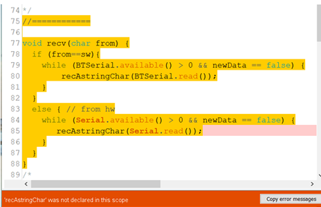
Start with a function that looks like the one we show here of lines 75 to 88 in yellow.
By now you know that having code you will need to try the Compile operation. It gets you an error, like the ones we had earlier, of the type: function name not declared in this scope. We are going to need initially another stub to let us compile past this error, so add one in like before, and make sure you can now get a compile without errors.
Now lets have a look at the code we've written for the recv() function.
It is quite clean, you can see the use of the 'if' condition to produce the two parts of the function referred to above.
The code inside the 'sw' part and the 'hw' part is of the same form, and I will describe it here.
The first of the pair of lines in each case is the start of a while loop. If you're not familiar with while's you can look it up in the Arduino.cc/Reference site for the explanation and examples. Here we wait 'while' the inbuilt 'Serial' function has not received any character(s) and because the newData variable has been turned off (i.e. the newData == false condition is true). As soon as a character - or more than one character - is received the while will 'drop through' to the second line in this pair. That will then call on the recAstringChar(char); function to handle the current character. This pair of lines will then alternate while (or for as long as) there are any characters still requiring to be received. Once they are all done the while state ends, allowing the if or else next level up to end, and in turn allowing the rec(char); function to end. Thus a full message has now bee received.
Step 12: Write the Receive Sub-function - Part 1


We now need to write the function called recAstringChar(char); . You see from the comment to line 50 here at its top, that its job is to update two buffers with copies of the incoming serial message. [It turned out while I was trying to get this all working that one thing I learned was that I needed two different buffers - or at least that was the easiest way to get round some problems, hence it kinda evolved into needing 2 buffers, so I just made them.] I've called one buffer: receivedData , and the other: receivedChars.
The buffers are global variables, so they are declared at module level, see lines 9 and 10 of the common tab. There are other variables declared inside this function that therefore have local scope- shown in lines 51-54 here. This is not the place to explain the differences between globals and locals, but there is more info on this in https://www.arduino.cc/glossary/en/ under Local and Global.
You can also find out all about the data types and type-modifiers: static, boolean, byte, const, char in https://www.arduino.cc/reference/en/#variables, shown here.
The main program flow in this function is controlled by the if at line 56 here, and its corresponding else at line 74. This deals with two scenarios
a) [from line 74 on] when the received message is beginning. This happens when the startMarker is spotted - this has been defined as the '<' character, which is why whenever we test the sketch we always begin our string with that character. If we don't then nothing will be processed as being received, it will all be ignored just as though we are typing nonsense at the 'Serial Monitor' keyboard prompt.
b) [lines 56 to 73] which receives all the other characters, whatever they are, but they only deal with characters after a valid start has happened (a '>' has been received as in a) above.)
In these lines (from 74 to 78) we put that received < into one of the buffers (receivedData[0]) but not in the other one. We adjust the buffer pointer (variable: char ndx) to point to the next spare buffer position (receivedData[1]) using the post-increment command (++) in the line ndx++; , and we set the in progress flag to true.
The program flow in this part of the function is controlled by the if at line 57 here, and its corresponding else at line 65. This deals with two scenarios
a) [from line 65 on] when the received message is ended. This happens when the endMarker is spotted - defined as >, which is why whenever we test our sketch we always end our string with that character. One of the things that happens when the end character is received is that the global flag (technically variable) newData is set true just as the function ends, so that the function that called our sub-function (the calling function: recv(char); ) can 'know' that valid new data has been received complete.
b) [lines 57 to 64] which receives all the other characters, whatever they are. It just busily parks them neatly in rows in both of the buffers.
Step 13: Write the Receive Sub-function - Part 2

It might help to give an example of what the 2 buffers look like when they have been populated. If we were to key in <7,9>enter, the buffers would have the characters shown in them:
So now you can see we have one buffer which is exactly all the same characters as we first typed in, and one buffer which just has the two values and a separating comma. Now we have some code which can receive the characters we type in at the Serial Monitor keyboard, we can move from CDIO phase I to O, typing-in some strings and seeing what happens. Upload the code to the Master Arduino, open up the Serial Monitor and try typing in something valid, like <08,04> enter. Do you receive an echo on the Serial Monitor screen like the one shown here?
Step 14: Write the Transmit and Parse Functions

First for the Transmit
So now we have received a string, we can write the transmit function: tran(char); to replace its stub. This will allow us to send a string from the Master to the Slave Arduino,
so make sure both devices are plugged in and connected together to test this new functionality.
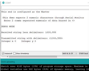
Enter this function as shown here in lines 117 to 133. As you will recognise, it has two parts, one to transmit to the USB channel (hardware UART) and one to transmit to the other Arduino (software UART.) This should compile error-free, and you can immediately upload the sketch and see what happens. This time I will send <1000,999> . Do you get the result shown?
The screen shot is interesting because the Received string… should look correct as before, and the Transmitted string … should now look correct. However note that the Integer conversion has not worked. There is still a bit more code to add to make that work.
Step 15: Write the Transmit and Parse Functions


Then for the Parse
This is a piece of code that parses the string received to fetch out the numeric partial strings and converts them to integer values. It is the void parseData(); function of the main loop
Replace the parse stub with the code shown in lines 98 - 113. Upload it, and let's see if the problem we were having with the 2 integer values is now fixed. Lets try <49,98>.
Yes, it does work, as shown, the integers found are 49 and 98.
Step 16: Finale!
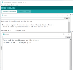
This data has gone right round the loop from the PC through the Master through the slave and back via the Master again to the PC again. With the finished version of common uploaded into both Master and slave ends, and with debug mode turned off now, we get to see data correctly received at both ends as shown here.


Participated in the
Arduino Contest 2020


