

Introduction: Sense Room Temperature and Display in LCD Using Simulink and Arduino UNO

Sensing and displaying room temperature using Arduino is very common and you will find loads of tutorial instructablesand other similar sites. But, I have not found any tutorial anywhere how to do this using Matlab/Simulink. Mathworks has got a very good support package for Arduino but only for individual Digital and Analog pins. Till now they have not released any support for LCD. Here in this tutorial I will describe how to work with LCD using Arduino Uno and Simulink. The user need not to do any programming in Arduino IDE. Everything will be done using Simulink.
Step 1: Procure the Stuffs
1. Arduino UNO Board - 1 no.
2. Breadboard - 1 no
3. 16x2 LCD Module - 1 no.
4. 1k Potentiometer - 1 no.
5. Jumper wires - 20 no. (Male to Male)
6. Laptop/PC with Matlab/Simulink License (I used R2014b)
7. Simulink support package for Arduino should be installed
8. LM35 Temperature Sensor
9. LDR - 1 no. (Optional, if you need to control the LCD backlight depending on the environment lighting.)
Step 2: Connect the Components Together
The LCD module has 16 pins. Out of which we need to connect the following pins
Pin 1 - Ground
Pin 2 - +5V
Pin 3 - Contrast Adjustment
Pin 4 - H/L Register Select
Pin 5 - H/L Read/Write
Pin 6 - H/L Enable
Pin 11 - DB4
Pin 12 - DB5
Pin 13 - DB6
Pin 14 - DB7
Now connect the Arduino pins
LCD RS pin to digital pin 12
LCD Enable pin to digital pin 11
LCD D4 pin to digital pin 5
LCD D5 pin to digital pin 4
LCD D6 pin to digital pin 3
LCD D7 pin to digital pin 2
LCD R/W pin to ground
1K resistor: ends to +5V and ground wiper to LCD VO pin (pin 3)
If you want the back light on then connect PIN 15 and 16 of LCD to +5V and GND of Arduino through a 220 Ohm resistor.
More can be found here
The connection for the temperature sensor is
GND to GND
Vcc to +5V
Vout (Middle pin) to A0
More you can find here
Step 3: Simulink - Building the S-Function


Simulink is a graphical programming language where you can easily work with hardware and as well as physical modeling. Mathworks provides support package for most (All?) of the Arduino boards. But unfortunately, there is no built in support block for LCD. Therefore I decided to make one for my own. You need a little bit knowledge of programming for this, and it is very easy and here is the step by step procedure, (I assume that you have a little bit knowledge of Matlab and SImulink environment)
- Open Simulink and create a new project first. Now go to the Simulink library browser and drag a block named 'S-function builder' into the project. (It is available under SImulink>User-Defined functions).
- Now double click the block to open it and you should see something similar to figure 1. We will edit the properties here to make the S-Function work.
- First we will name the block. I have named it 'lcd_print_plain_text'.
- Now in the 'Initialization' tab, put number of discrete states = 1.
- Now go to next tab i.e. 'Data properties'. Here we can set the input and output ports and modify their data types. I have created an array of 32 characters as my LCD is 16x2. That means I will send the value to be written in LCD for each block (Whether there is some value or it is NULL) in each loop cycle.
- As our LCD block is an output block, therefore there will be input port only. I have created one input port named 'lcdinput' (Refer figure 2). As it is an array of 32 characters, we have to write 32 in the Rows. In the data type attributes sub-tab, we need to set the data type of our input variable 'lcdinput' as uint8. (Refer figure 3)
Next, we need to go to the 'Libraries' tab and declare some functions. In the includes textbox the following code need to be written, (Please refer the text document attached. It seems that I cannot put the code here properly. Sorry for that) (Refer figure 4)
Next we will go to the 'outputs' tab and write the following code there. (Please refer the text document attached. It seems that I cannot put the code here properly. Sorry for that) (Refer figure 5)
Next we will go to 'Discrete Update' tab and write the following code there. (Please refer the text document attached. It seems that I cannot put the code here properly. Sorry for that) (Refer figure 6)
Finally the S-function is ready to build. The build button is located at the top rihght corner of the window. While generating the code remember to keep the checkbox of 'Generate wrapper TLC' in 'Build Info' tab checked. (Refer figure 7)
Attachments

Step 4: Creation of Simulink Model

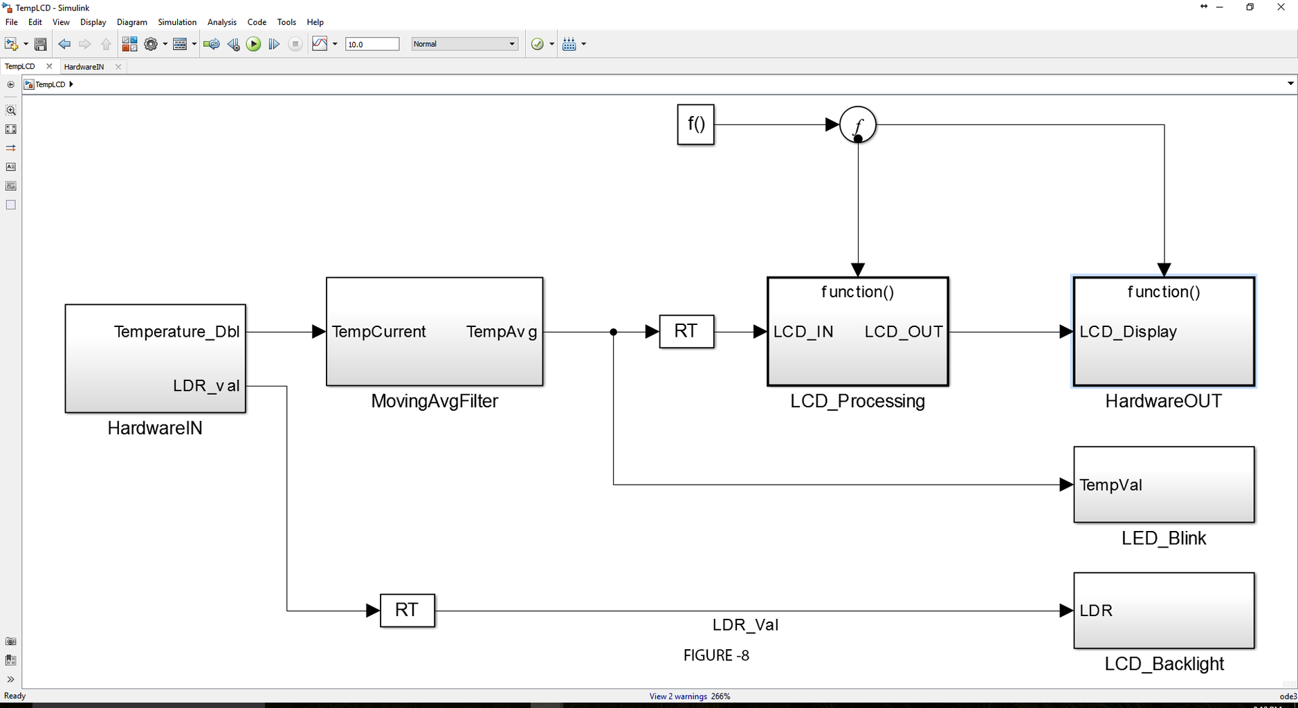


The figure 8 shows the complete Simulink model for the project. It is having 3 parts
- Hardware input - Where data from sensors will be read
- Data processing - It is a moving average filter.
- Hardware output - Processed data will be written to the display using this block.
Other important components of the model are
- Rate transition blocks (Given by RT) - They are used as there are signals of different rates.
- Function call generator block (Given by f()) - It is used to write in the LCD only after a specified period of time. This time should be an integer multiple of the program loop time.
Now going to the Hardware Input block we will read the temperature sensor input pin (It is the Analog pin where the temperature sensor is connected) and the LDR pin data. We also need to convert the temperature data to degree Celsius. I am using LM 35 temperature sensor and its calibration chart is easily available in the internet (just google it). We need to use the following formula for converting,
Temp_DegC = SensorReading/((SensorIPVoltage_mV/ADCResolution)/SensorSlope)
SensorReading = This value will be obtained from sensor
SensorIPVoltage = 5000
ADCResolution = 1023
SensorSlope = 10
(Refer fig 9)
Next is the filter. Here I have used a 10 point moving average filter. you can use any other filter also. (Refer fig 10)
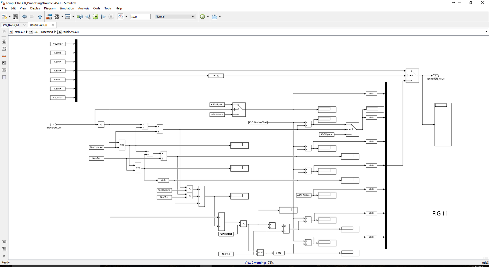
Finally we need to do some work for sending the data to LCD. As Simulink cannot send string and char type data we have to use some alternative method. Here I am sending the ASCII value of what to be printed in the LCD. For this we need to create a list variables made up of of possible characters to be printed with their ASCII values. (Like A, a, B,b,.......,Z,z, 0,1,2.....,9 and of course the decimal sign (.) and space ( )).
The temperature data is in double type data and we have to convert it to a string. If you see figure 11 the procedure will be clear.
Bus is used to convert the 1*1 data to an array.
Finally we will connect the bus to the S-Function created in previous step. ( Refer figure 12).
Now we can run the model to see the output in LCD.


