

Introduction: Sensors


What sets robots apart from basic machines is their ability to both sense and respond to phenomena in the physical world. To do this, they use sensors. A sensor works by converting physical output from the world into a signal that can be understood by a microcontroller. Since all sensors in some way measure properties in the physical world, and robots are able to take actions to affect the physical world, a feedback loop is created. It is a robot's ability to have an active and 'intentional' role in their environment that sets them apart from most other machines.
Step 1:
While there is no fixed rule about the type of sensor a robot must have, we can go over a few that robots commonly use.

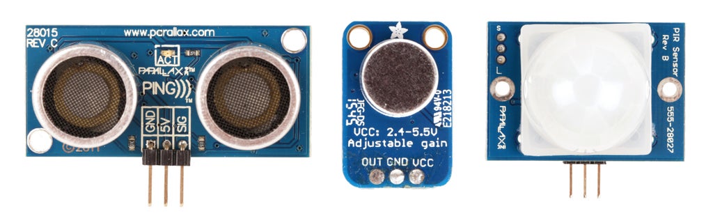
One of the most popular is the ultrasonic rangefinder. This sensor sends out a highly directional ultrasonic "ping" and counts the time it takes for the sound to bounce off the object and return to the sensor. This sensor is good for detecting the presence of objects that are between 1" and 120" (12') away. It is good for sensing non-moving obstacles, but not good for sensing motion.

To sense if people in a space are moving, you would want to use an IR motion sensor. This sensor has a pre-defined viewing angle which differs between models, which basically means that is has a field in front of the sensor that it can detect movement within. This field tends to increase in width the farther away from the sensor you go. It does not tell you how far people are, but is very good at identifying if people are present and moving.

There is, however, an IR sensor which is good for sensing distance. This sensor works in much the same way as the PING sensor, but instead of measuring sound that reflects back, it measures IR light. These sensors vary widely in the distance ranges they measure, so it is important to check a sensor's datasheet to make sure it is the range you are looking for before buying one. They tend to be highly precise in their measurements, but they are also typically slightly more expensive than ultrasonic sensors.

If you want your robot to measure the amount of visible light in a space, you can use a photocell. Aside from measuring light, a photocell and some LEDs can be fashioned into a crude color sensor. This is because some colors reflect light better than others. Thus, this sensor can be used to identify and follow a black line drawn on the ground. For an example of how to build such a sensor, check out my telepresence robot. The downside for using a sensor for this purpose is that it is affected by ambient light.

You can also use the robot to measure sound. This sensor is largely just a pre-amplified microphone. This sensor is easiest to interface with if you are just measuring the volume of sound. Listening for commands or frequencies is very difficult for the Arduino because typically it requires too much processing power to do anything too advanced. Albeit, it is possible for more advanced coders to accomplish. Typically, if you want to do advanced audio processing, you would use a shield or module to listen for frequencies or voice commands. An example of this, again, can be found in my telepresence robot.

A robot collision switch is typically just a lever switch with some sort of extender arm attached to the lever. This creates a large mechanical advantage, and gives the switch a hair trigger. It will alert the arduino almost immediately upon being touched. They also make commercial versions of this for use as mechanical safety switches. These are good for really big robots, such as the rubber bumper switch used in my robotic bedframe.
Step 2:
Once you have selected a sensor, there is no single standard way for sensors to communicate information to a microcontroller. Each sensor needs to be interfaced with in a manner appropriate to it. Fortunately, most sensors are sending data in a predictable manner as either a resistance, analog voltage, digital voltage, or data signal.

An analog sensor produces a signal which is constant and roughly proportional to whatever is being measured. Put another way, it puts out an uninterrupted voltage signal, or produces a variable amount of resistance in the circuit. As a general rule, these sensors tend not to be quite as accurate as digital sensors, but they do tend to be cheaper and more robust. For many non-precision robotic applications, an analog sensor is more than suitable.

Many analog sensors are resistive which means that they have a fluctuating amount of resistance-based on whatever they are measuring. Examples of such sensors are a photocell, FSR (force sensitive resistor) or bend sensor. These sensors can be read by a microcontrollers analog input using a voltage divider. These sensors tend to be passive, meaning that they will function and produce a reading even without an input voltage. Put another way, you can read their resistance with a multimeter even if it is not part of a powered circuit.

To test out this sensor in action, wire a 10K resistor in series with a photocell. Connect their junction to pin A0 on the Arduino. Connect the remaining resistor pin to ground, and the remaining photocell pin to 5V power. Once the wiring is complete, open the Arduino software and upload File > Examples > 01.Basics > AnalogReadSerial. Finally, to see it in action, open the Serial Monitor.

Some analog sensors such as temperature sensors, photo transistors, and IR rangefinders are voltage-based and will produce a signal between 0V and 5V. This can be read directly by an Arduino's analog pin. These sensors are usually active, meaning that without an input voltage they will not be powered on or do anything. They are typically interfaced using the Arduino in exactly the same manner as resistive sensors. However, it is important to keep in mind that they are outputting a current, as opposed to changing resistance for those rare instances where interfacing with them deviates.

A digital sensor has a discrete voltage output, meaning the signal is either on or off. Put into electronics terms this means the signal is either high or low, or 1 or 0. The digital signal can be as simple as on and off, or it can be toggled on and off fast enough to communicate using a binary (1 or 0) data protocol.
The Arduino, in turn, is able to interpret these pulses and understand what is being communicated. It is a bit like someone is communicating with the
Arduino in morse code by tapping on a switch connected to an
input pin. Except, in this case, it is happening really - really - really - fast.

Arguably, the most basic digital sensor is a switch. It provides a signal which is either on or off depending on whether it is pressed or not. In normal circumstances, this involves human input. However, you can use switches as collision switches on robots such that when the robot bumps into something, it warns its microcontroller brain to stop driving in that direction. This type of sensor would be considered passive and is rare as far as digital sensors go.

A more typical digital sensor that produces a basic high or low output is an IR motion sensor. It is able to sense motion by picking up on human heat waves. This type of sensor just tells you if there is human movement, or not.
To try it out, connect the 5V pin to 5V on the Arduino, ground to ground, and the DIG pin to digital pin 2 on the Arduino as pictured. Next, open the Arduino software and load up File > Examples > 01.Basics > DigitialReadSerial. Finally, point the sensor away from you (to avoid constantly triggering it), and open the serial monitor.
Finally, there are advanced sensors such as ultrasonic rangefinder sensors and accelerometers that communicate with the Arduino using a complex custom protocol or binary data signal (such as serial). These sensors are specialized modules (more on that in the next lesson) that have their own IC or microcontroller preconfigured to provide accurate sensor readings to another device.
Often these sensors will require reading their datasheet to understand how to interface with them. For instance, the PING sensor, which is a ubiquitous brand name ultrasonic sensor produced by Parallax, has a pin which is used as both an input and an output. It needs to be sent a 5V pulse from the microcontroller, and then the same pin needs to be configured as a digital input and monitored for the return signal. However, if I hadn't just told you and you didn't read the documentation, you would have a lot of trouble figuring this out.
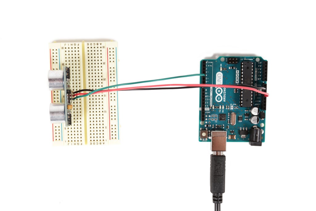
If you have a PING sensor, plug it into the breadboard and wire its pins to the Arduino as follows:
Ping 5V to Arduino 5V
Ping Ground to Arduino ground
Ping Signal to Arduino digital pin 4
Once the wires are connected, upload the following code and open the Serial Monitor:
/* Ping))) Sensor

   This sketch reads a PING))) ultrasonic rangefinder and returns the
   distance to the closest object in range. To do this, it sends a pulse
   to the sensor to initiate a reading, then listens for a pulse
   to return.  The length of the returning pulse is proportional to
   the distance of the object from the sensor.

   The circuit:
	* +V connection of the PING))) attached to +5V
	* GND connection of the PING))) attached to ground
	* SIG connection of the PING))) attached to digital pin 7

   http://www.arduino.cc/en/Tutorial/Ping

   created 3 Nov 2008
   by David A. Mellis
   modified 30 Aug 2011
   by Tom Igoe
   modified again 02 Apr 2016
   by Randy Sarafan


   This example code is in the public domain.

 */

// this constant won't change.  It's the pin number
// of the sensor's output:
const int pingPin = 4;

void setup() {
  // initialize serial communication:
  Serial.begin(9600);
}

void loop() {
  // establish variables for duration of the ping,
  // and the distance result in inches and centimeters:
  long duration, inches, cm;

  // The PING))) is triggered by a HIGH pulse of 2 or more microseconds.
  // Give a short LOW pulse beforehand to ensure a clean HIGH pulse:
  pinMode(pingPin, OUTPUT);
  digitalWrite(pingPin, LOW);
  delayMicroseconds(2);
  digitalWrite(pingPin, HIGH);
  delayMicroseconds(5);
  digitalWrite(pingPin, LOW);

  // The same pin is used to read the signal from the PING))): a HIGH
  // pulse whose duration is the time (in microseconds) from the sending
  // of the ping to the reception of its echo off of an object.
  pinMode(pingPin, INPUT);
  duration = pulseIn(pingPin, HIGH);

  // convert the time into a distance
  inches = microsecondsToInches(duration);
  cm = microsecondsToCentimeters(duration);

  Serial.print(inches);
  Serial.print("in, ");
  Serial.print(cm);
  Serial.print("cm");
  Serial.println();

  delay(100);
}

long microsecondsToInches(long microseconds) {
  // According to Parallax's datasheet for the PING))), there are
  // 73.746 microseconds per inch (i.e. sound travels at 1130 feet per
  // second).  This gives the distance travelled by the ping, outbound
  // and return, so we divide by 2 to get the distance of the obstacle.
  // See: http://www.parallax.com/dl/docs/prod/acc/28015-PING-v1.3.pdf
  return microseconds / 74 / 2;
}

long microsecondsToCentimeters(long microseconds) {
  // The speed of sound is 340 m/s or 29 microseconds per centimeter.
  // The ping travels out and back, so to find the distance of the
  // object we take half of the distance travelled.
  return microseconds / 29 / 2;
}
Step 3:
Sensors we have covered in this lesson are by no means the only sensors you might ever use. There are more sensors in this world that I can possibly go over. Other things you might want to sense include acceleration (accelerometer), color, natural gasses, electromagnetic fields (hall effect), orientation in space (gyro), human touch (capacitive), wireless signal strength, weather, and air pressure (to name a few). Chances are if there is something out there you want to sense, there is a tool out there to do it. All you need to do is track it down and figure it out.
For a comprehensive index of existing sensors, check out the sensor list on Wikipedia.


