

Introduction: Sigfox Electric Meter


Description:
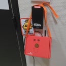
This project will show you how to get your electricity consumption using a small device plugged onto your electrical meter. Note that it only works with the "Compteur Electrique Triphasé agréé EDF, ECS, 60A / 40KWh Multi Tarifs". This model is very common in France.
Basically, on this electric meter, a LED blinks every time a Wh is consumed. So the idea is to record this blink and link it to a counter and then every hour send it to a server using Sigfox network.
Which microcontrollers will be used?
We will be using the Akeru dev kit.
Other dev kits are available on Sigfox Partners Network.
Does it work on all electric meters?
No unfortunately, it only works on the "Compteur Electrique Triphasé agréé EDF, ECS, 60A / 40KWh Multi Tarifs" which are very common in France. Feel free to try to adapt it and share your solutions!
How long does it take to make it?
All the source code is available on Github. So, within an hour or two, you will be able to make it work.
If you want to print the adapter, I have been using 3D hubs and I received it in two days.
Do I need any previous knowledge?
You don't need any previous knowledge although knowing Arduino and CAD design is a plus.
Who am I?
My name is Louis Moreau, I'm an intern at Sigfox. My mission is to create prototypes and PoC using Sigfox network. I want these projects to be fun and instructive. I want to show you how easy is it to develop the first steps of your ideas. I will try to make this tutorial as complete as I can. Do not hesitate to ask me for more details if needed : Github
Contrib:
Emmanuel Nhan (@nhanmanu)
Step 1: Understand Sigfox
What is Sigfox?
Sigfox is a connectivity solution dedicated to the Internet of Things. The operated network is currently operating in +15 countries, on every continent.
Focused on tiny messages (up to 12 bytes) & low energy consumption, it currently powers 7 million devices. Various Sigfox-compatible technical solutions are available, from different silicon vendors. This project uses an Arduino shield from Atmel (see below)
Step 2: Hardware Requirements


In this tutorial, we will be using :
- An Akeru
- a 10 kΩ resistor
- a photocell resistor
- a breadboard
- few male to male cables
Step 3: 3D Printing


Software requirements:
I've been using the free software FreeCAD to design the plug. You can download the sketches on both formats .stl or .fcstd on the Github's project: https://github.com/luisomoreau/sigfox_electrical_meter
Use the .fcstd file to open it with FreeCAD if you want to modify it.
Use the .stl format if you just want to print it (https://github.com/luisomoreau/sigfox_electrical_meter/blob/master/electrical_meter_plug.stl)
Printing the plug:
I've been using the 3D Hubs platform to print the plug: https://www.3dhubs.com It costs around 4.5€ depending on the quality you choose.
Step 4: Arduino Code

Install Arduino IDE:
You need to install the Arduino IDE : https://www.arduino.cc/en/Main/Software
Choose your OS, download it and install it.
Basic understanding of Arduino programming:
Before starting each program, we start with two "base" functions: void setup() and void loop().
- void setup() is executed in first. It is used to initialise the card.
- void loop() is executed infinitely (as long as power is provided)
See more on https://arduino.cc
Include Akeru Libraries:
First, you need to download the Akeru libraries: https://github.com/Snootlab/Akeru
Then, place the Library in your Arduino Libraries folder, usually at:
- Linux: /Home/your-username/Documents/arduino/libraries
- Windows: \My Documents\Arduino\libraries
- Mac: /Users/your-username/Documents/Arduino/libraries
Download source code:
Download or clone the repository: https://github.com/luisomoreau/sigfox_electrical_meter
Open the .ino file within your Arduino IDE
Run the code:
Try now to compile the code using the check button on the upper-left corner and upload it using the button just next. (Don't forget to add the serial port if it is not automatically detected: Tools > Serial Port > your Arduino port).
Step 5: Using the Sigfox Backend


Dev Kit Activation
To activate your dev kit, go to https://backend.sigfox.com/activate and choose your provider.
Depending on your location, pick your country and then fill the device's ID, the PAC number and your details. Both ID and PAC number are written on your dev kit or your box. Check your emails and log in. Your device will appear in your account. Click on its ID and go to messages to check if you received anything.
Custom Data Payload:
Now, click on "Device Type" -> your device type -> Information -> Edit (upper right corner)
You will see a block "display type". Select "Custom" and then add "conso::uint:8" into the custom configuration field.
View messages:
Click on "Device" -> Your device ID -> Messages to see the messages received by Sigfox network
Step 6: View Your Data Using TheThings.io


This platform is an example on how to view your data.
You can use another platform or service simply by setting up a callback (view next step). Different platforms are available on https://partners.sigfox.com
First, go to https://sigfox.thethings.io create an account and then create new IoT project.
Fill the form as shown in the picture.
Step 7: Create a Callback in Sigfox Backend

Now that TheThings.io is in place, we need to configure callbacks in Sigfox Backend.
Sigfox offers a callback service: every time a message is received by the network, we set up the way we want it to be forwarded to our application server. URL, content-type, request body, ...
Log in your sigfox backend account and go to "Device Type", then click on card's name.
On the menu at the right, you will be able to see at the bottom "callbacks".Click on "New" (upper-right corner) and then "Custom callback".
Choose the following configuration:
- Type: DATA UP-LINK.
- Channel: URL.
- Url pattern: Paste your previous subscription URL from thethings.iO.
- Use HTTP method: POST and click Ok.
Step 8: Going Further


This project can be improved. Below are few improvements ideas:
- Use interruptions on Arduino code to get the raising values of the electrical meter blinking LED instead of getting this values on the loop function. It will be more precise and save some battery.
- Eventually, use transistors to get this values as digital values.
- Use custom code in thethings.io to parse the data.
Whatever you think can be improved, feel free to share it!
Thank you for your attention :)
I will be glad to answer your questions (Twitter or Github)

Participated in the
Internet of Things Contest 2016


