

Introduction: Simple Variable 30v 2A Power Supply From Scratch


This simple power supply will be able to provide 30v at 2A.
It uses a LM317 to vary the output with efficiency.
It can be used to power anything from circuits to motors. It will take you less than two hours to assemble it, assuming that you have done projects related to electronics before, and have some soldering skills.
Step 1: Gathering the Materials
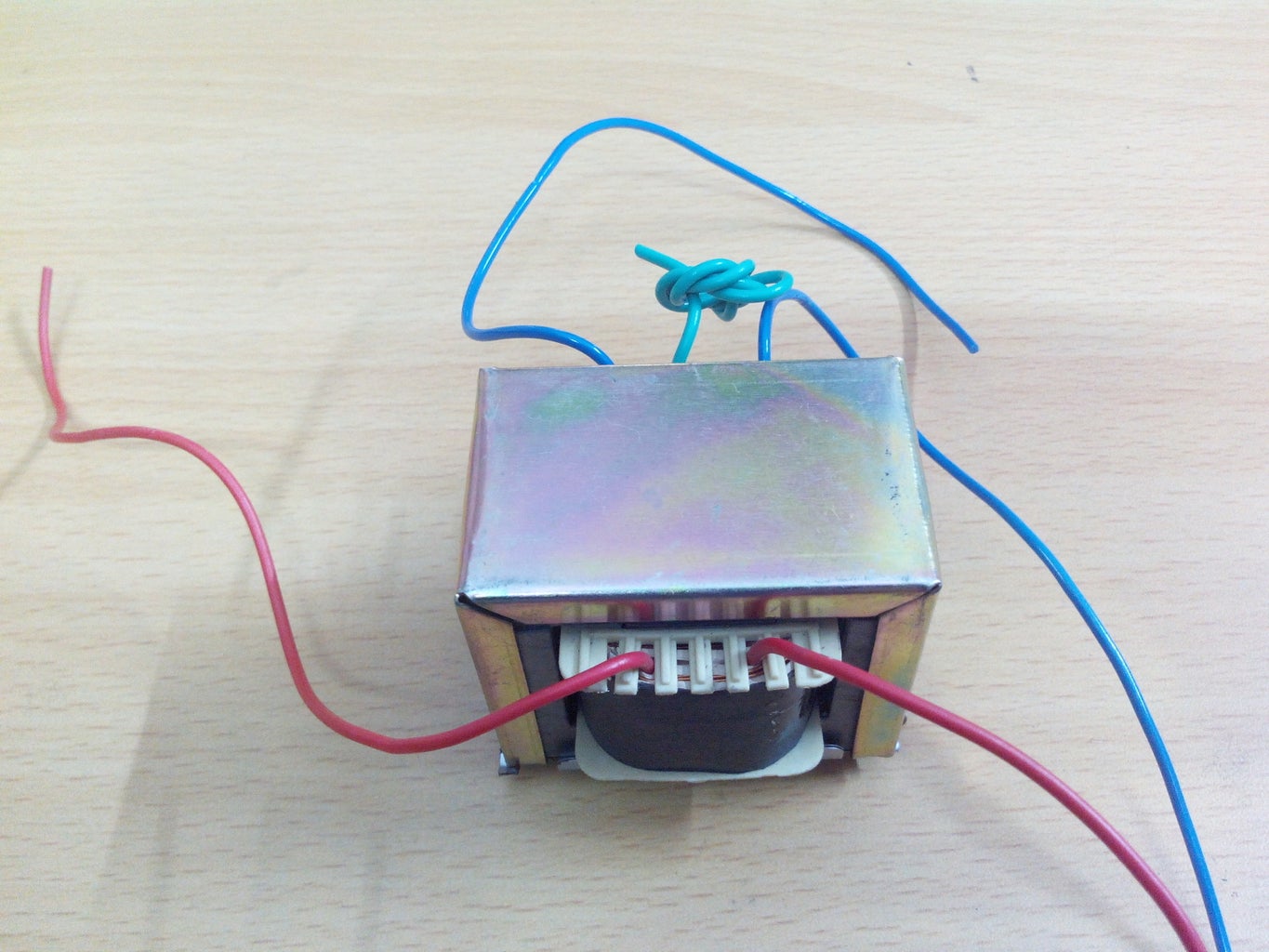


Transformer
The transformer is the heart of the build. I got a 12-0-12 transformer, which means that it has three outputs, +12v, 0v(ground),and +12v.
Rectifier IC
This is required to convert AC to DC.
alternatively, you can use a conventional rectifier made of four diodes.
LM317 and Heat sink
this is the variable voltage regulator IC. it may get hot, and to dissipate that heat, we need a heat sink.
Vriable resistor(10k)
This and the LM317 will vary the voltage.
if you use a fixed resistance, you will get a fixed output.
2000uF 35v capacitor
PCB
AC switch with indicator
Fixed resistance of 2k(2.2k)
Wires connected to a plug head for AC input
Project Enclosure box
DC Digital Voltmeter
you can buy all these things online
Step 2: Assemble the Circuit

-Mount the rectifier and ICs according to the circuit.
-The transformer steps the voltage down to 12v-0v-12v according to the three tappings.
-Since it is AC, there is no + and -. So we can take the two 12v wires and get 24v.
-The rectifier IC converts the AC to DC.
-The +ve from the rectifier goes to the input of the regulator.
-the center pin of the regulator is connected to a combination of a fixed resistance and a variable resistance in series. this is so that the resistance never drops to zero.
-The output +ve goes to the base of your transistor(2n3055). the transistor amplifies the current to the current rating of the transformer, in this case it is 2 A. In my case, the voltage regulator could not handle currents more than 10 mA, which prompted me to use the transistor.
-Connect the voltmeter in parallel to the output leads.
-After all that is completed, connect the wire with the plug head to the transformer through a AC switch with the indicator. Insulate the connections in the switch with hot glue or electrical tape. The switch will also act as a fuse.
-Make sure to connect the output leads to the alligator clips. It is recommended for you to use alligator clips with a cover.
Step 3: Encase It
Draw the places you want to cut on your enclosure box and cut it using a rotary tool. If you don't have one, you can heat up a knife and slice through the plastic box like butter(thats what i did). the placement depends on your box and components.
As far as possible, try to isolate the transformer from the DC components. use hot glue or electric tape to insulate the circuits and components.
A problem i faced was with mounting the potentiometer. it had a nut , but the thread was too small; the plastic panel on the box was too thick. To solve this, use a hot knife to gently melt a small layer of the plastic from the outside. then you can use pliers and tighten the nut on the potentiometer.
Step 4: Precautions
-Make sure to NEVER short the outputs. This will apply a load on the circuit and it may get fried.
-Always disconnect the Power supply before making adjustments to it.

Participated in the
Invention Challenge 2017

Participated in the
Power Supply Contest


