

Introduction: World's Simplest Line Following Robot


Here in this instructable I'm going to show you how to make the World's simplest Line following robot. Simplest in terms of number of parts used and the complexity of the circuit.
Most of the line following robots on the internet use complex circuits with microcontrollers and op amps. And the algorithms used like PWM(Pulse Width Modulation),PID(Proportional Integral Derivative) are tough to understand and implement for a newbie or a hobbyist.
As an engineering student, I have studied all these things. But why not make it simple for others?
So I designed this circuit for a line following robot which uses the same principle as is used by most of the circuits available on the internet.
So let's start!
Step 1: Parts Required
LM358 dual op amp - 1
BC547 transistors - 2
1K 1/4Watt resistor - 2
330 ohms 1/4Watt resistor - 2
470 ohms 1/4Watt resistor - 2
10K potentiometers - 2
Infrared LEDs(IR LEDs) - 2
IR sensors (Photodiode) - 2
DC geared motors 30 RPM or 60 RPM - 2
Chassis for mounting motors and PCB - 1
Step 2: Circuit Diagram


Here's the circuit for the line follower.
The circuit is shown only for one side(i.e., one motor and one op amp). You need to make the same circuit using the 2nd op amp IC present in the same chip- LM 358( dual op amp means it has 2 op amps inside).
Note-
Connect the components on a general purpose PCB except for the sensors(IR Leds and Photodiodes).
You need to make sensor connections on a separate board as shown in the pictures above.
The distance between the sensors should be equal to or slightly greater than the width of the track on which you want your robot to work. In my case I'm using a black electrical tape of width 18 mm.
So the distance between the sensors is 18 mm in my case.
This robot follows black track on white background. If you want to make a robot that follows white track on black background then you need to invert the connections.
Interchange the connections on the inverting and non-inverting terminals of the op amp.
Step 3: Working

The working of this circuit is very simple.
Here the op amps are used in open loop configuration. To be specific they are being used as a comparator.
A comparator is a circuit which compares the voltage on one of the input pin with a reference voltage set on another pin and gives either a high(+Vcc) or low(0V or -Vee) output.
LM358 has 2 op amps inside. Both are used as comparators. Each comparator is connected to one sensor and output to one motor through a transistor.
The reference voltage is set using a 10K pot on the inverting terminal of the op amp.
Now suppose the sensor is placed on a white surface. The IR rays from the IR led will be reflected and these are sensed by the photodiode. This increases the voltage of the photodiode and it crosses the reference voltage set by the 10K potentiometer.(You need to do this manually by experimenting on the surface on which you want your robot to work.) So the output goes high and the motor starts working. If the sensor comes on black surface, black colour absorbs all the IR rays, so output of op amp is low and hence motor stops.
When the track is curved, one of the sensor is on white surface and one is on black track. So one motor is running and one is stopped, the bot takes a turn.(Shown in image above.
The above picture is the courtesy of ermicro.com
Please read calibrationdetails otherwise you won't be able to get it working.
Step 4: Calibration- the Most Important Step
Please follow the instructions carefully. If you don't follow each and every step given here, your line follower won't follow the track.
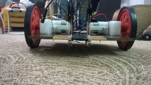
Follow these steps once the robot is ready. All the parts and the sensor PCB is firmly attached to the chassis at a certain distance from ground.
1)Place the robot on a black surface(both the sensors are on black surface). The distance from sensor to ground should be kept fixed to calibrate the robot. Variation in the distance between sensors are ground may cause the robot to not follow the track. So please attach all the sensors firmly to the chassis.
The black surface should be made of same material as your track.
In my case I used the same electrical insulation tape for the calibration purpose.
2)Now the motors maybe running or they may be stopped depending on the current position of the potentiometer.
While the robot is still on black surface, adjust the potentiometer such that both the motors just stop.
3)Now do not move the potentiometer shaft. Carefully place the robot on a white surface. The motors should start running. Your robot is calibrated now.
4)Make a track on the white surface using the same black material you used for calibrating.
Switch on the bot and keep it on the track.
It works perfectly and follows the track as efficiently as a micro controller based one.

Participated in the
Tech Contest

Participated in the
Robotics Contest


