

Introduction: Simplest Wireless Electricity Transmission Experiment


Hello everybody, today I want to show you very interesting and very simple wireless electricity transmission experiment, in fact the simplest air transformer. I really like circuits like this, impressive and elementary in the repetition.
Step 1: Components


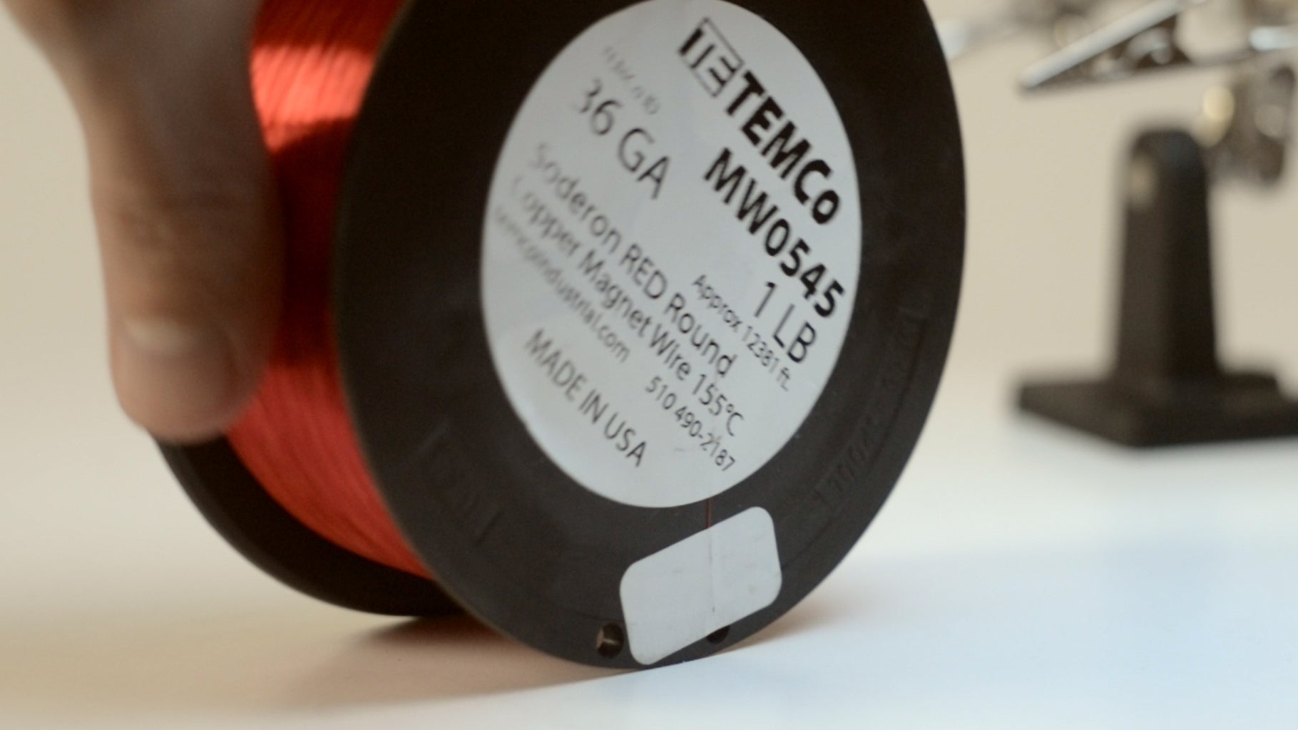

So lets start, we need transistor 2n3904, or almost any similar NPN transistor, any LED, also we need cooper winding wire 0.1-0.5mm about 15 meters, I use 0.13mm or 36AWG you if like. You can find a suitable wire in almost any needless transformers.
And that's it, it’s all components we need for this project.
Step 2: Coils


First we need to make 3 coils, 30, 60, 90 turns each, for a temporary frame I used 1 ½ inch pipe, place a piece of tape sticky side out, glued one end of the wire, and wind 30 turns, than fix the coil and pull it out from the frame, leave 10 centimeters wires for installation. Same with coils on 60 and 90 turn. In general you can not worry about the frame, and wind coils on the fingers, I'm just trying to make it accurate.
Step 3: Assembly


Now let’s look at the circuit, it consist of two parts, two coils and a transistor – is a generator, and the third coil and LED – indicator. Getting to the assembly, clean winding wires, solder transistor legs, then you need to solder one end of the 60 turns coil to the middle terminal of the transistor, to the base (if you are using 2n3904, if different, better search for the datasheet), I also pu pice of heat shrink tube in vainly, than you understand why. Solder the rest end of coil to firs transistor’s terminal it’s emitter. Next step – solder solder any end of 30 turns coil to third transistor’s terminal it’s collector. Solder a little pice of regular wire to the first transistors leg, it’s going to be power. Now turn of the LED and rest 90 turns coil, simply solder the diode terminals to the ends of the coil, the polarity is not important. At this assembly is completed.
Step 4: Power-on


Device need power supply of 1.5 to 9 volts, in my case it’s two AA batteries in series. Place coils 1 and 2, one above the other, plus is going to remained end of 30 turns coil, and wire we solder to first transistor terminal to minus. Place the indicator coil nearby. Last step is touch transistor's base with something metal to start generator, now you understand why heat shrink tube in vain? And vuala! LED lights - device works! If it doesn’t try to flip over one of the coil, or change ends of 60 turns coil.
Step 5: Final

Participated in the
Circuits Contest 2016


