Introduction: Smart-Greenhouse

Hello markers,
We are a group of three students and this proyect is part of the subject called Creative Electronics, a Beng Electronic Engineering 4th year module at the University of Malaga, School of Telecomunication (http://etsit.uma.es/).
This project consists of an intelligent greenhouse capable of module the bright of a bulb depending on the sun’s light. It also counts with sensors which measure humidity, temperature and brightness. To show all the information there is a lcd screen. Aside, we make a program using processing that allow you to change the bright of the bulb manually in case you want to, with a 3D environment.
Step 1: Materials
- 1 Photoresistor
- 1 Sensor temperature/humidity DHT11
- 1 Lcd LCM1602C
- 1 Protoboard
- 1 Box (https://www.ikea.com/es/es/productos/decoracion/plantas-jardineria/socker-invernadero-blanco-art-70186603/)
- 1 Bulb
- 1 10k-Ohm resistor
- 1 SAV-MAKER-I (alternative to Arduino Leonardo). If anyone desires to make this board instead of using Arduino Leonardo we add the link of github where you will find all the required information (https://github.com/fmalpartida/SAV-MAKER-I).
The dimmer circuit, which let the variation of the light’s intensity of the bulb, is based on one maker desing (https://maker.pro/arduino/projects/arduino-lamp-dimmer). Used materials:
- 1 330-Ohm resistor
- 2 33k-Ohm resistors
- 1 22k-Ohm resistor
- 1 220-Ohm resistor
- 4 1N4508 diodes
- 1 1N4007 diode
- 1 Zener 10V 4W diode
- 1 2.2uF/63V capacitor
- 1 220nF/275V capacitor
- 1 Optocoupler 4N35
- MOSFET IRF830A
Step 2: Temperature/humidity Sensor

We used the sensor DHT11. This
sensor provide us digital data of air humidity and temperatura. We consider is important to measure this parameters because it influences the growth and the care of the plant.
To program the sensor we had used the Arduino library DHT11. You have to add the DHT11 library to your Arduino library folder. We include the library for download.
As you can see, we add an image to show how is the sensor’s conection.

Step 3: Light Sensor


To do the light sensor we used a photoresistor, that is a variable resistor with light’s change, and a 10k-Ohm resistor. In the following image is shown how to do the connections.
This sensor is really important because all the data it gets, is used to regulate the brightness of the bulb.
Step 4: LCD Screen

We used the lcd LCM1602C. The lcd allow us to show all the information we capture with all the sensors.
To program the lcd we had used the Arduino library LCM1602C. You have to add the LCM1602C library to your Arduino library folder.
We add an image to show how to connect the device.
Step 5: Dimmer Circuit


The first way that comes to mind when using an Arduino and having to dimmer a light is to use PWM, so that's the way we went for. In doing so we were inspired by the well known design circuit by Ton Giesberts (Copyright Elektor Magazine) which do PWM of an AC source. In this circuit, the power voltage for driving the gate is supplied by the voltage across the gate. D2, D3, D4, D5 form a diode bridge, rectifying the tension in the circuit; D6, R5, C2 also serves as rectifier, and R3, R4, D1 and C1 regulate the voltage value across C2. The optocoupler and R2 drive the gate, making the transistor switch according to the PWM value provided by the Arduino board. R1 serve as a protection for the optocoupler LED.
Step 6: Programming SAV-MAKER-I
The function off this program is to read and show all the information that our sensors are receiving. Besides we module the light with a PWM signal depending on the light values. This part forms the automatic regulation.
The code is added below.
Attachments
Step 7: Programming With Processing
The function off this program is to represent grafically what’s going on with the greenhouse in real time. The grafic interface shows a 3D greenhouse with a bulb (which turn on or off at the same time it do it in real life) and a plant. In addition, it represent a sunny day or a starry sky depending on the bulb’s state . The program also let us to have the control of the bulb in a manual way.
The code is added below.
Step 8: Making the Board

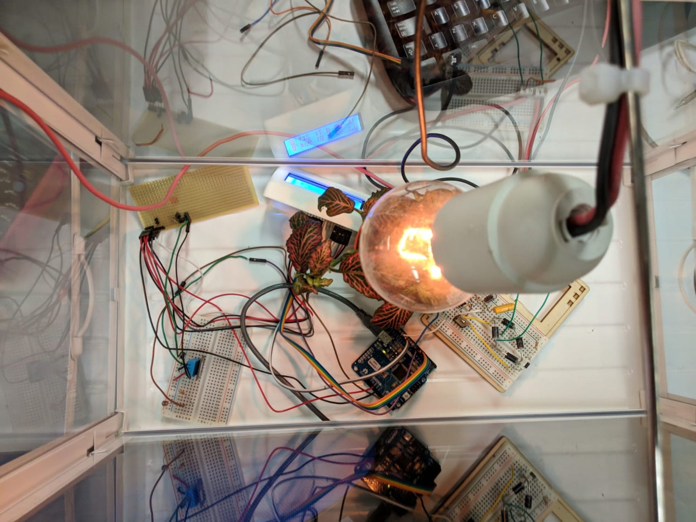
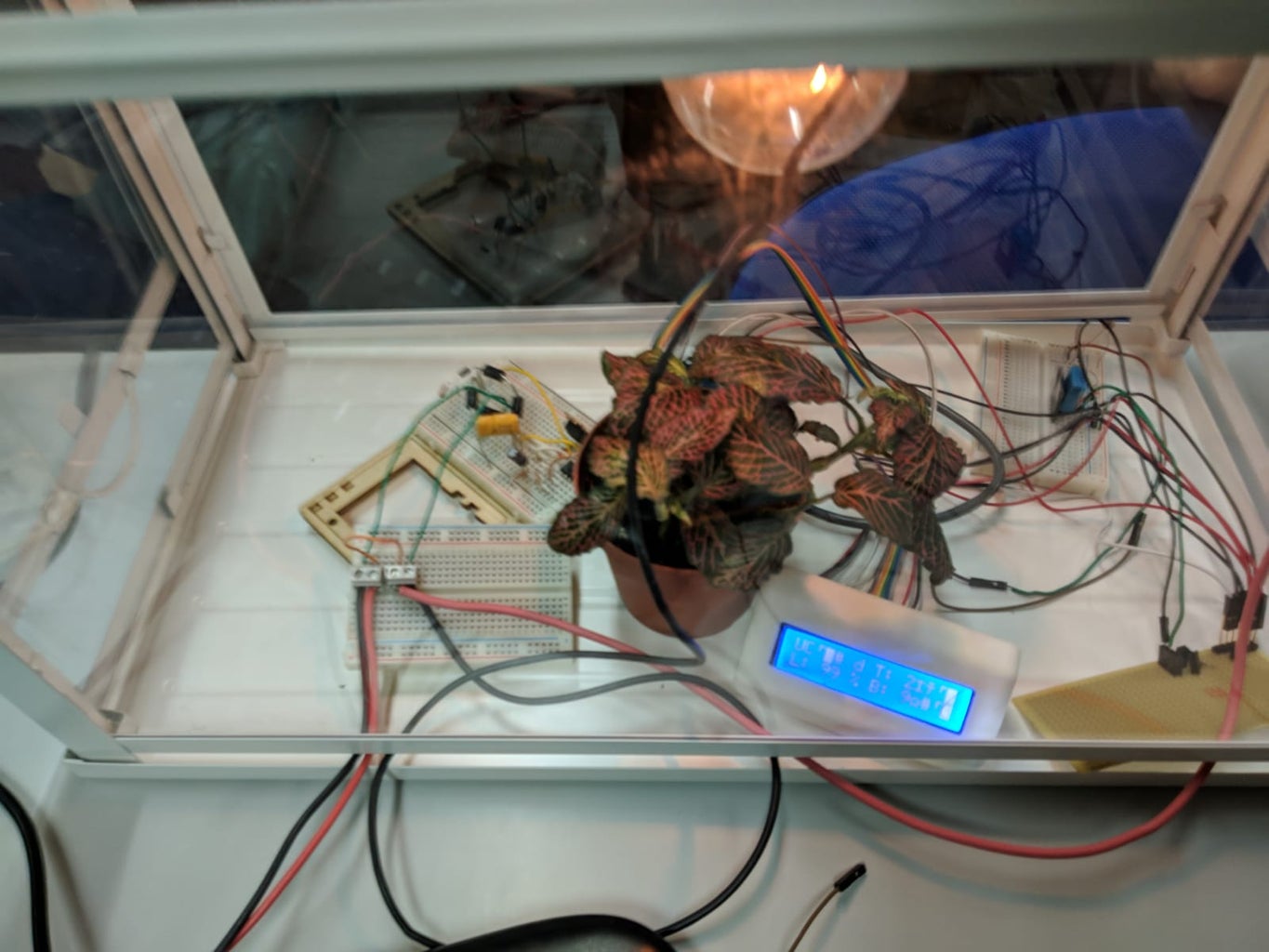
As you can see in the added photos, we put all the components on the protoboard following the image of the connections we put.
Step 9: Final Result