

Introduction: Smart Phone Controlled LED Lights Using HC-05 and Arduino UNO


Bluetooth Module HC-05 is one of the most commonly used piece of hardware which allows you to quickly prototype your ideas which require a wireless control/connective element. This project is a very quick demonstration of how we can interface this module with an arduino board and get going with multiple applications.
Components Needed:
1. Arduino Uno and programing cable
2. HC-05 Bluetooth Module
3. Jumper Wires
4. Power Bank (or just plug into your laptop/desktop/mobile charger[5V 1A])
5. LED Red, Yellow, White
6. Bread Board
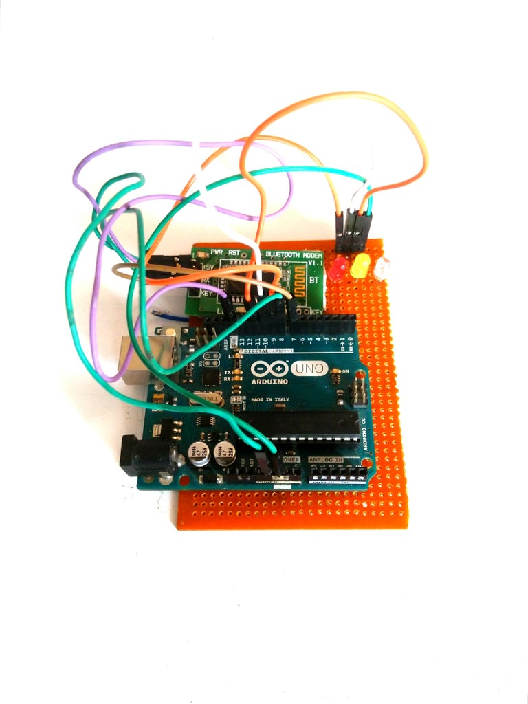
Step 1: Wire Up the Arduino

Make sure you get the connections right. This module uses serial communication to talk to Arduino (any micro controller), so you have a choice of using the default serial interface via pins 0&1 or can choose from any other digital pins including A0-A5 (A0 is D14 - A5 is D19) via the software serial library. The software serial library is available by default in the standard Arduino IDE package.
We are using pins D7 and D6 as our Rx and Tx respectively. Please note the Rx on the module is connected to the Tx on the controller and Tx on Module is connected to the Rx on the Controller.
Step 2: Code for This Application
#include <SoftwareSerial.h>
SoftwareSerial mySerial(7, 8); // RX, TX
char character; boolean flag=false; int Red=9,Blue=10,Green=11; String s1 = "1", s2 = "2", s3 = "3"; void setup() { // set the data rate for the SoftwareSerial port mySerial.begin(9600); Serial.begin(9600); pinMode(Red,OUTPUT); pinMode(Blue,OUTPUT); pinMode(Green,OUTPUT); mySerial.print("Press 1:Red, 2:Yellow,3:White "); digitalWrite(13,0); } void loop() // run over and over { String Data = ""; flag=false; while(mySerial.available()) { character = mySerial.read(); Data.concat(character); flag=true; //digitalWrite(13,1); //Serial.print("Received : "); delay(100); //Serial.println("foo"); } if(flag) { Data.trim(); Serial.println(Data); if(Data.equals(s1)) { digitalWrite(Red,1); digitalWrite(Blue,0); digitalWrite(Green,0); Serial.println("Red ON"); } else if(Data.equals(s2)) { digitalWrite(Red,0); digitalWrite(Blue,1); digitalWrite(Green,0); Serial.println("Blue ON"); } else if(Data.equals(s3)) { digitalWrite(Red,0); digitalWrite(Blue,0); digitalWrite(Green,1); Serial.println("Green ON"); } } }
Step 3: Connect Your Smart Phone


We will use a simple Bluetooth Terminal App Download Bluetooth Terminal for Android
1. Pairing your Hc-05 Module with the android phone.
Power up the circuit and switch on Bluetooth on your smart phone.
Go to Bluetooth settings> Scan for available devices (Refer image 1)
Select the Bluetooth Module currently available and enter the Default Password :1234 (AT commands allow you to change this and a lot more cool stuff with some degree of security)
PS: you only need to pair the device once i.e. the first time you connect a particular module
2. Using the Terminal App
Simply log into the Terminal app you downloaded previously. Select Connect Device- Secure>Select the module
Now you are up and running. Send 1/2/3 to switch on Red/Yellow/White LED.
PS: If you have paired multiple hc-05 modules with the phone, it would be wise to either change their names (using AT commands) or remember their mac address(a difficult choice).


