

Introduction: Smart Solar Lamp


Generally, solar lamps are used but they get discharged as they are ON at midnight when there is no use of light.Therefore to save battery and the Smart solar lamp is a solution in which light will glow only when there is any motion within 3-5 meter of its range.
Instead of glowing whole night for insects, it will only glow for us(Human).
Smart solar lamp uses solar panels, rechargeable battery, LDR and PIR sensor.
So let's design it.
Step 1: Requirements


1.Solar panels-select according to requirements. For example if using 9v battery select 12v solar panels as there are losses in the circuit.
2.Battery-choose as per output required. Lead acid cand be used or Li-ion are the best one as these are light weight and have more life cycles.
3.LDR
4.PIR sensor module
5.LM317-it is a volatge regulator and its output range is 3-37v.
6.Resistor(220ohm,47k,1k)
7.Zener diode(10v)-it is use to prevent overcharging of battery.
8.LEDs
9.3-BC547 transistor-it is used as switch in circuit.
10.Diode-to prevent reverse flow of current
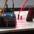
Step 2: Circuit and Working

Design circuit as shown in fig. on breadboard or PCB
Starting from solar panels-12v solar panel generally gives out 13.2-14v. Therefore select 12v solar system for 9v battery charging. A diode is used in series of the panel to prevent reverse flow of current when there is no sunlight.
IC LM317 is used to give out constant desired voltage as per required. Its output voltage can be varied using variable resistor R as shown in fig.
Zener diode is used to break circuit whenever battery terminal voltage is above 10v. when voltage is above 10v current flow through zener diode and hence provide base voltage to the base of BC547, which result in grounding of LM317 output terminal and hence charging of battery stops.
Furthur LDR and BC547 combination is use as a switch which give out voltage to VCC of PIR sensor whenever there is dark.
PIR sensor gives out voltage whenever there motion in its range of 3-5m which further pass to base of bc547 and which result in Collector emitter current and completion of circuit.
Overall LED glows whenever there is dark and there is motion in front of Smart solar panel.
Step 3: Conclusion
Resistor and Zener diode values can vary as per Panels, LDR and battery used.
Calibrate as per required.
Hope U enjoy in designing it
If any kind of doubt feel free to write.

Participated in the
Green Electronics Contest 2016

Participated in the
Sensors Contest 2017

Participated in the
Make it Glow Contest 2016


