

Introduction: Smart Trash Can - for a Smart City


Overflowing garbage bins have been another cause of concern for residents in developing countries. With increase in population, the scenario of cleanliness with respect to garbage management is degrading tremendously. With the already prevailing diseases, the open containers are proving to be a breeding place for germs. Traditionally, municipalities operate on weekly routes to pick up trash and recyclables on designated days, regardless of whether the containers are full or not.
My project aims to optimize waste collection and ultimately reduce fuel consumption. When the bin are placed at a particular position smartphone is required to detect its particular latitude and longitude only once. This reduces the cost of overall system; as GPS will not be required then.
Basically, it will shoot sonar waves to know how much stuff is inside the container. We will also measure temperatures inside the container. Data collected from the sensors are sent over a cellular network (GPRS) for analysis and displayed on Ubidots web platform for customers. A list of containers to be collected can then be sent to drivers to plan an efficient route. The project will also include real-time monitoring of the civic body’s garbage vehicles using RFID. The vehicle owner has to flash his RFID card so that who and when and at what time garbage bin were emptied. It will help to curb laziness of the municipality’s garbage collectors.
Essentially, this project is about collecting the most amount of materials in the least amount of time to reduce costs and emissions along the way. Furthermore, this project is supposed to work with any type of container and any type of waste, including mixed materials, paper, glass, metals and fluids. Thus, there will be saving in fossil fuel due to optimized route for collecting garbage and also thus transportation cost.
By the end of this tutorial you’ll have a fully functioning IoT prototype, which gathers data from the sensors attached to the LinkIt ONE development board, transmits the data through a wireless communication channel (GPRS), and provides visualization using cloud services on any GPRS/Wi-Fi enabled device.
Step 1: Hardware Components Required


This section describes the hardware and electronics, in addition to a LinkIt ONE development board, needed to build prototype and provides details on how to put them together.
Step 2: Basic Info and Initial Setup


MediaTek LinkIt™ ONE development platform enables you to design and prototype Wearables and Internet of Things (IoT) devices, using hardware and an API that are similar to those offered for Arduino boards. The platform is based around the world’s smallest commercial System-on-Chip (SOC) for Wearables, MediaTek MT2502 (Aster). This SOC has inbuilt:
- CPU core: ARM7 EJ-S 260MHz
- Memory: 4MB RAM, 4MB Flash
- Dual Bluetooth 2.1 (SPP) and 4.0 (GATT)
- GSM and GPRS modem
While the development platform also has Wi-Fi, GPS, Audio codec, and SD card connector.
For more info:
http://labs.mediatek.com/site/global/developer_too...
http://www.seeedstudio.com/wiki/LinkIt_ONE
First three images show basic information about MediaTek LinkIT ONE development platform.
While the other images show initial setup you have to inform on the various components like connecting antenna, inserting sim card etc.
{These setups are very important!! So please go through it once!!}
Step 3: Schematic and Connections


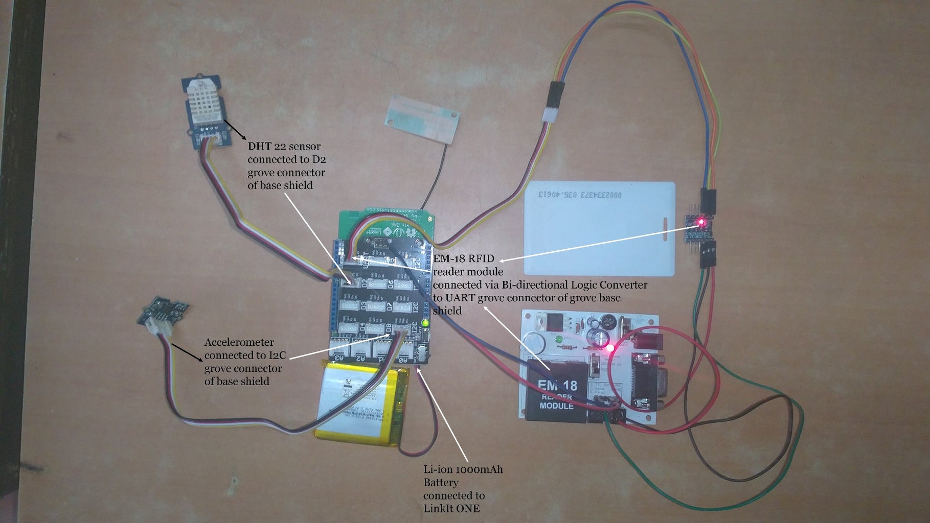


The components are connected as follows:
- GSM antenna connected to GSM Antenna Port. The antenna is provided in the LinkIt ONE development board’s kit and supports GSM 2G standards.
- Grove base shield is connected on the top of LinkIt ONE.
- Grove DHT 22 sensor is connected to the D2 grove connector of grove base shield i.e. to voltage (3.3V), ground (GND), D2 pins of LinkIt ONE. DHT 22 measures temperature and humidity. The detecting range of DHT 22 sensor is 5% RH - 99% RH, and -40°C - 80°C. And its accuracy satisfyingly reaches up to 2% RH and 0.5°C.
- Grove - 3-Axis Digital Accelerometer (±16g) sensor is connected to the I2C grove connector of grove base shield i.e. to voltage (3.3V), ground (GND), SCL and SDA pins of LinkIt ONE.
- DYP ME007v1 Ultrasonic sensor’s connection:
- Vcc - 3.3V of Grove Base shield i.e. to 3.3V of LinkIt ONE
- Gnd - Gnd of Grove base shield i.e. to Gnd of LinkIt ONE
- Trigger - To D12 of Grove base shield i.e. of LinkIt ONE
- Echo - To D11 of Grove base shield i.e. of LinkIt ONE.
- EM-18 RFID Reader Module’s connection:
- Connecting power supply to the module
- Connecting Gnd of EM-18 to the Gnd of Grove Base shield
- Connecting Tx of EM-18 to Rx (D0) pin of Grove base shield via Bi—directional logic converter (5V to 3.3V).
- LinkIt ONE development kit contains 1000mAh Li-Po battery. Connect it to the LinkIt ONE Board.
Step 4: Ubidots Account and Arduino IDE Setup


Ubidots account setup:
Ubidots offers a platform for developers that enables them to easily capture sensor data and turn it into useful information. Use the Ubidots platform to send data to the cloud from any Internet-enabled device. The service is also very affordable with up to 500,000 data point uploads (or dots) a month, with 1 Month of historical storage for free.
Register on Ubidots and activate the account to prototype your own devices and applications. You can also set triggers and alerts that can automate responses to data thresholds you set. Finally, all this is accessed by a powerful, standard and fairly well documented Application Programing Interface (API).
Arduino IDE setup for LinkIt ONE:
If you haven’t built a LinkIt ONE project before, this section describes the steps you need to follow before commencing this project.
Download LinkIt ONE developer’s guide:
http://labs.mediatek.com/site/global/developer_to...
Arduino Software:
Download and install Arduino software version supported by the LinkIt ONE development board as described in the LinkIt ONE developer’s guide.
For windows users:
http://labs.mediatek.com/site/global/developer_to...
For Mac users:
http://labs.mediatek.com/site/global/developer_to...
In addition to providing your coding environment, the software is used for monitoring the development board.
LinkIt ONE SDK Installation and Configuration:-
Download and install the LinkIt ONE SDK.
http://labs.mediatek.com/site/global/developer_to...
Follow the instructions in the LinkIt ONE developer’s guide to install and configure the SDK.
In addition to providing the API and tools to use Arduino, the SDK also provides a tool to upgrade the development board firmware and reset it to the factory default settings.
Step 5: Working
After ubidots and arduino ide setup completed open the final stc (Smart Trash Can) code compile and verify it. Then connect your linkit one and upload the code. Now disconnect the usb power supply to LinkIt ONE and then connect the sensors, RFID reader, GPRS antenna, 2G sim card and the Li-ion battery.
LinkIt ONE initialises the ubidots account details in it's code, then the sensors, GPRS and serial ports.
It has two serial port one is the usb and the other is serial1 which is on digital pin 0 and 1. We have connected RFID reader to serial1 port of LinkIt ONE. The board tries to update the value to Internet (i.e. ubidots account) after every reporting interval of 20 seconds which can be changed as per the customer requirements. In between it tries to read data from RFID card so that it can know if authorized person is trying to empty it or not and also to upload the authorized persons rfid number to ubidots so that the municipality will know who and at what time the trash can was emptied.
After every 20 seconds the board reads the data from the sensors (ultrasonic, accelerometer and temperature), also the battery level and updates it to ubidots account (Internet).
For information about how to send data from LinkIt ONE to Ubidots, I have created a simple project with full descriptions:
https://www.hackster.io/alpha007/temperature-humid...
Working of sensors and modules:
1) Grove - Temperature and Humidity Sensor Pro (i.e. DHT 22 sensor)
Links:
a) https://learn.adafruit.com/dht?view=all
b) http://www.seeedstudio.com/wiki/Grove_-_Temperatu...
2) Grove - 3-Axis Digital Accelerometer(±16g) (i.e. 3-axis IC ADXL345 accelerometer sensor)
Links:
a) https://learn.adafruit.com/adxl345-digital-accele...
b) http://www.seeedstudio.com/wiki/Grove_-_3-Axis_Di...
3) DYP ME007 5-pin Ultrasonic sensor
The basic principle of how ultrasonic sensor works:
- Using digital pin send about 10us high level signal on trigger pin of sensor,
- The Module automatically then sends eight 40 kHz and detect whether there is a pulse signal back.
- IF the signal comes back, then the duration for which the echo pin was high gives us the the total time taken by sonar waves from sending ultrasonic to returning back after bouncing on a object. So we need to first divide time by 2.
We know,
Distance=Speed * Time;
In this case,
Object distance = (high level Echo time/2) ×velocity of sound (340M/S),
The range of the sensor is from 2-500cm.
Velocity of sound (in m/s) = 340
Since the duration for which the echo pin remains high is in microseconds
Therefore, Velocity of sound (in cm/us) = (340 * 100)/1000000 = 1/29
Therefore, Object distance = (high level Echo time in us/2) x (1/29 cm/us)
= high level Echo time/58 cm
Links:
a) https://code.google.com/p/megapirateng/wiki/dypme...
b) https://alselectro.wordpress.com/2013/03/08/ardui...
4) EM-18 RFID Reader Module
Links:

Step 6: Result


Hope you understood the project!!

Participated in the
Arduino All The Things! Contest


